5 PalmAI M3 Device User Manual
The User Manual is available for Max and Standard. Use the tabs below to switch between editions.
- Max
- Standard
5.1 Device Overview and Installation
This section describes the main components of the M3, its installation environment, wall and turnstile installation methods, access control wiring, startup procedure, and palm scan precautions.
5.1.1 Device Exterior and Interfaces
The main components of the M3 include the NFC card reader area, display, palm scan camera module, concealed reset button on the left side, pigtail interfaces, and speaker.
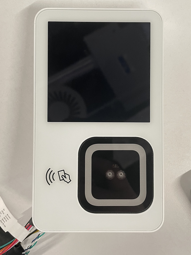
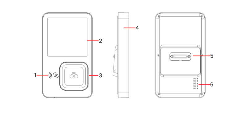
| Component | Description |
|---|---|
| NFC card reader area | Reads access cards. Card-reading capability depends on the on-site access control configuration. |
| Display | Shows device pages, operation prompts, and processing results. |
| Palm scan camera module | Captures and recognizes palm information. |
| Concealed reset button on the left side | Press it with a paper clip or similar pointed tool to perform a hardware restart if the device malfunctions. |
| Speaker | Plays voice prompts and notification sounds. |
| Pigtail interfaces | Include USB HOST, relay, Wiegand, and RS485 interfaces. |
The pigtail interfaces serve the following purposes:
| Interface | Purpose |
|---|---|
| USB HOST | Connects supported USB peripherals. |
| Relay | Outputs a dry-contact signal for connection to a dedicated access control power supply or door lock control circuit. |
| Wiegand | Outputs Wiegand signals to the access controller. |
| RS485 | Communicates with the access controller over an RS485 bus. |
Note
The M3 does not support PoE power. Use the supplied 12 V power adapter.
5.1.2 Indicator Lights
| Light status | Device status |
|---|---|
| Dim blue | Sleep mode |
| Dim white | Standby |
| Bright white fill light | Registering or recognizing a palm |
| Flashing orange | The palm is too close to the device |
| Green on | Recognition succeeded |
| Red on | Recognition failed |
5.1.3 Installation and Operating Environment
The M3 is intended for indoor or sheltered semi-outdoor environments. Observe the following requirements during installation and use:
- The device is not waterproof. Prevent liquids and dust from entering it.
- Do not use the device in extremely cold, hot, or humid environments or near heat sources.
- Do not drop, strike, throw, or bend the device.
- Use the device in a clean, low-dust environment, and leave sufficient clearance around it for heat dissipation.
- Keep accessories and disassembly tools out of the reach of children.
- Do not install the device near a window or outdoors where there is strong backlight. If necessary, adjust the device angle so that light falls evenly on the user's palm.
- Adjust the installation height to the average height of on-site users. For details, see "5.1.4.1 Wall Installation."
5.1.4 Installing the Device
5.1.4.1 Wall Installation
An 86-type junction box is recommended for wall installation. Depending on site conditions, set the installation height between 1.4 and 1.6 m.
- Route the access control wiring harness through the round hole in the bracket.
- Secure the bracket to the 86-type junction box using the M4 screws supplied with the device.
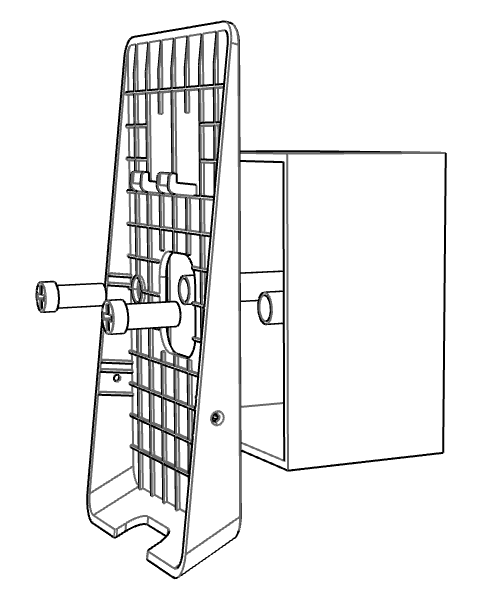
- Connect the access control harness to the device pigtail, then arrange the harness inside the junction box without pinching or pulling it.
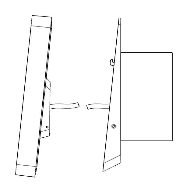
- Align the slots on the device with the tabs on the bracket, then snap the device onto the bracket.
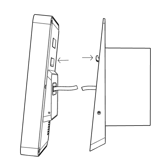
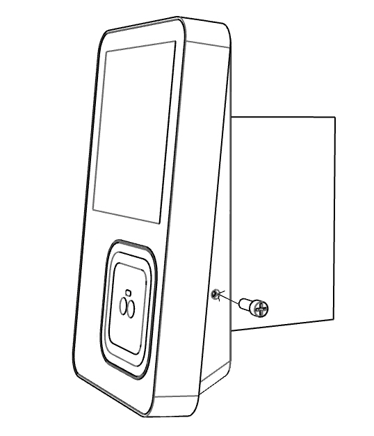
- Tighten the two M2.5 screws on the side of the device to secure it to the bracket.
Note
Disconnect all relevant power supplies before installation. Restore power only after confirming that the wire sequence, insulation, and fastening are correct.
5.1.4.2 Turnstile Installation
The M3 can output a door-open signal to an access controller through Wiegand or a relay. It can also connect through RS485 as required by the project integration. The access controller parses the signal and opens the turnstile. Follow the turnstile manufacturer's requirements for the mounting structure, cutout dimensions, and fastening method.
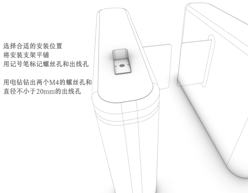
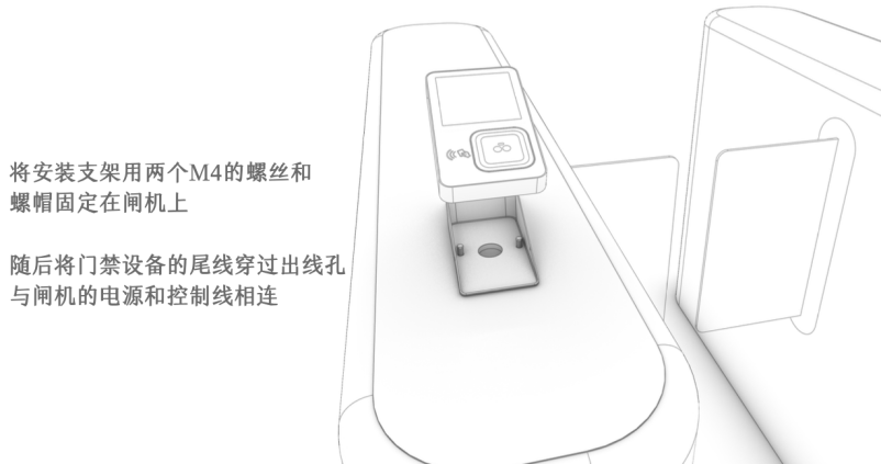
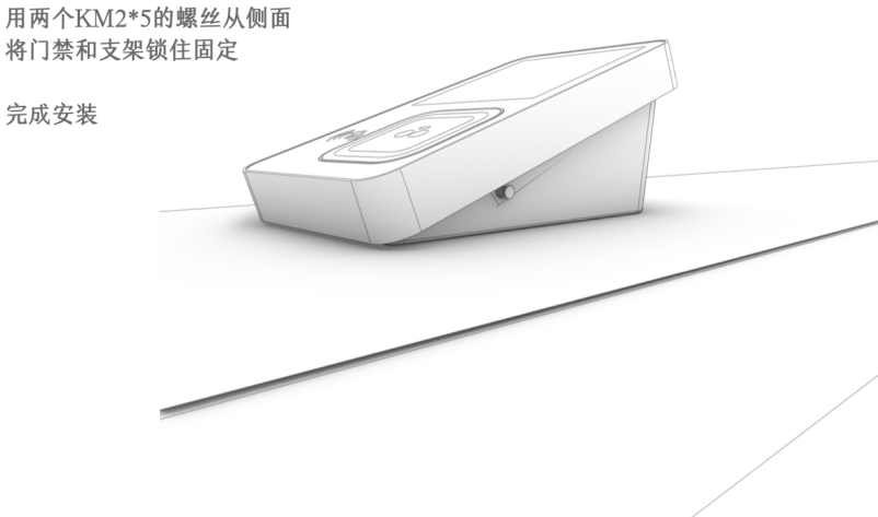
- Determine the device position and camera height based on the turnstile structure.
- Secure the device at the turnstile mounting position.
- Connect the device pigtail to the access controller according to the selected output method.
- Check the power supply, grounding, and signal wire sequence.
- After configuring permissions and device output in the Admin Console, test opening the turnstile with a palm scan.
5.1.5 Connecting Access Control Wiring
Before wiring, determine whether the site will use Wiegand, RS485, or a relay to open the door. Installation must be performed by qualified access control personnel.
5.1.5.1 Connecting Wiegand or RS485
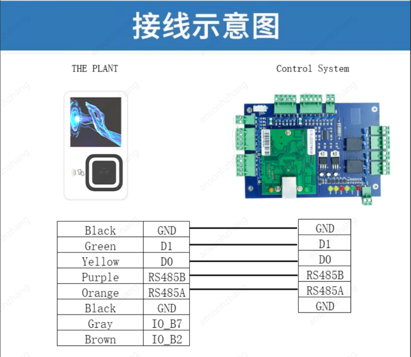
For Wiegand, connect the device's 12 V, GND, D0, and D1 wires according to the access controller interface definitions. Do not reverse D0 and D1. The device and controller must share a common ground.
For RS485, connect the positive and negative signal terminals of the device to the corresponding controller terminals, and ensure that all devices on the bus share a common ground.
Note
The Wiegand output format and byte order must match the access controller. For long cable runs, use suitable cables and keep them away from high-voltage power lines.
5.1.5.2 Connecting Relay Dry Contacts
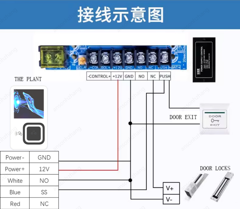
The relay outputs a dry-contact signal and can connect to the control terminal of a dedicated access control power supply. Select NO or NC according to the door lock type.
5.1.5.3 Connecting an NO or NC Door Lock
Door locks can be fail-safe (open when power is removed) or fail-secure (remain closed when power is removed). Select the lock type based on fire safety, security, and on-site business requirements, and wire it according to the NO, NC, and COM terminal definitions of the dedicated access control power supply.

The following example connects SS and NO for a fail-safe lock:
- P1: When power to the lock is removed, the lock physically releases and the door opens.
- P2: When the lock is powered but the M3 is not, the relay is open and the NO terminal is disconnected. The powered lock remains locked and the door stays closed.
- P3: When both the lock and M3 are powered, successful verification energizes the relay and cuts power to the lock, opening the door. If verification fails, the relay remains in its default state and the door stays locked.
Warning
Incorrect NO, NC, or power-circuit wiring may cause the lock to operate opposite to the intended behavior. Before powering the lock, use a multimeter to confirm the terminal states and verify the door-opening strategy during a power outage.
5.1.5.4 Receiving a GPIO Signal and Outputting a Relay Signal
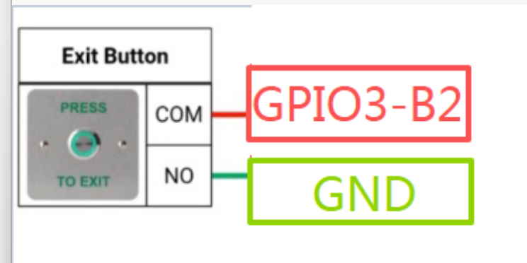
The M3 can receive an external GPIO signal and output a control signal through the relay. Wire the external device according to its voltage level, common-ground, and trigger requirements.

5.1.6 Powering On the Device
- Confirm that the device is securely installed and all cables are connected according to the interface definitions.
- Connect the supplied 12 V power adapter to the device power cable.
- Turn on the power and wait for the device to start and display the operation page.
To restart the device, open the Setting page and tap Device Restart, or press the concealed reset button on the left side with a paper clip or similar pointed tool.
5.1.7 Palm Registration and Recognition Precautions
Before registering or recognizing a palm, remove the protective film from the camera area and keep both the camera and palm clean.
- Extend the palm naturally with its center facing the center of the palm scan camera module.
- Keep the palm approximately 5–12 cm from the device.
- Hold the palm steady until capture or recognition is complete.
- Face the palm toward the device with a tilt angle of less than 30°.
- Keep the palm rotation angle below 180°.
- Do not obstruct the palm or use the device in strong backlight.
5.2 Initial Connection and Activation
5.2.1 Initial Connection Process
When connecting the M3 to the Palm Application Platform for the first time, complete activation in the following order:
- Configure Ethernet or WiFi and ensure that the device can connect to the network.
- Complete License authorization and confirm that the device is licensed to use palm scan algorithms.
- Enter the device name and Device SN in the Admin Console.
- Use the device to scan the activation QR code generated by the Admin Console to complete IoT activation and bind the device to the Admin Console environment.
- Associate the device with the appropriate scene in the Admin Console, then configure the scene strategy, verification rules, and user permissions.
Description
License authorization and IoT activation are separate processes. License authorization grants access to palm scan algorithms, while IoT activation connects the device to the current Admin Console environment. Complete both processes independently.
5.2.2 Configuring the Device Network
The device must be online to perform online authorization, IoT activation, configuration synchronization, verification record reporting, and OTA upgrades.
- Tap the settings button in the upper-left corner of the device home page.
- Enter the device settings password in the Please input password window. The initial password is
000000. - Tap Confirm to open the Setting page.
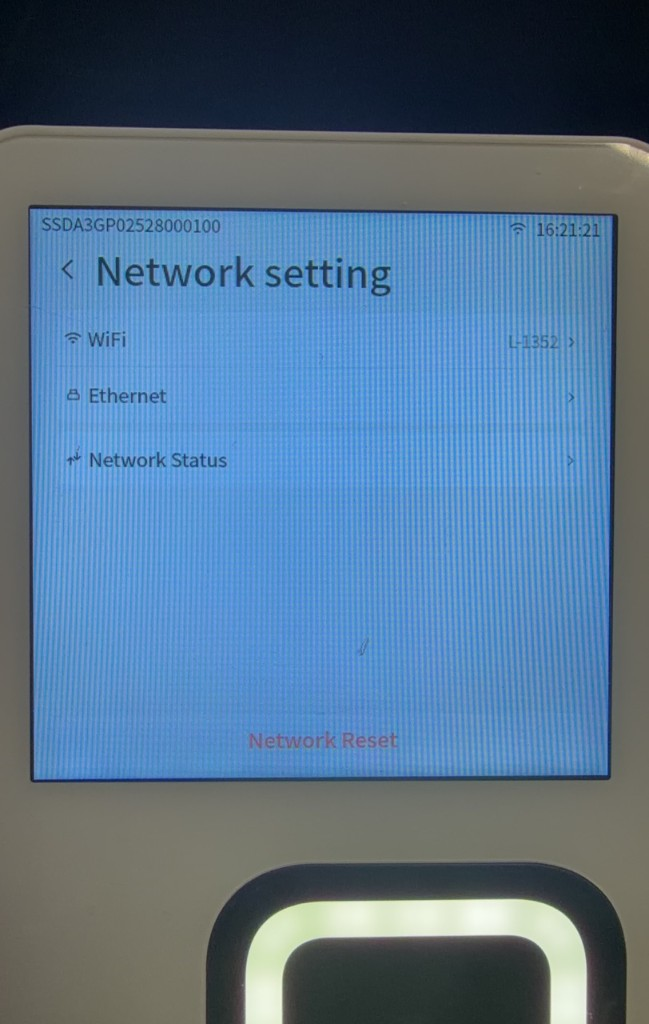
- Tap Network setting.
- Select WiFi or Ethernet based on the on-site network.
Tip
Use a wired network whenever site conditions permit. WiFi is not recommended for deployments with more than 10 devices.
Observe the following requirements when planning a wired network:
- A single Ethernet cable segment must not exceed 100 m; keeping it within 80 m is recommended. Do not place connectors in the middle of the cable, bend it sharply, or compress it.
- Use CAT5e or higher-grade cable and standard RJ45 connectors. Before installation, use a cable tester to check the wire sequence and connectivity.
- Protect cables with PVC conduit or wiring ducts. Use a separate power outlet for each device and avoid sharing a circuit breaker with other equipment.
- Do not cascade more than three switches on the same LAN.
| Number of devices | Recommended bandwidth and network topology |
|---|---|
| 1–4 | Shared bandwidth of at least 20 Mbps; devices can connect directly to a router. |
| 5–30 | Bandwidth of at least 100 Mbps with an enterprise-grade router and managed switches; use no more than four managed switches in one network. |
| 31 or more | A dedicated line of at least 100 Mbps, an enterprise-grade router, and Gigabit switches are recommended. Configure VLANs according to the project network plan. |
5.2.2.1 Connecting to a Wired Network
- Use an Ethernet cable to connect the network interface on the device pigtail to a router or switch.
- Go to Setting > Network setting > WiFi.
- Turn off the wireless network switch.
- Return to Network setting and tap Ethernet.
- Enable Ethernet.
Note
Enabling Ethernet and WiFi on the M3 at the same time causes a network conflict that prevents the wired network from operating correctly. Always turn off WiFi before using a wired network.
5.2.2.2 Selecting the Ethernet IP Mode
Ethernet supports two IP modes, DHCP and Static. The default is DHCP.
- Go to Setting > Network setting > Ethernet.
- Enable Ethernet.
- Tap IP Mode.
- Under Select IP Mode, select DHCP or Static.
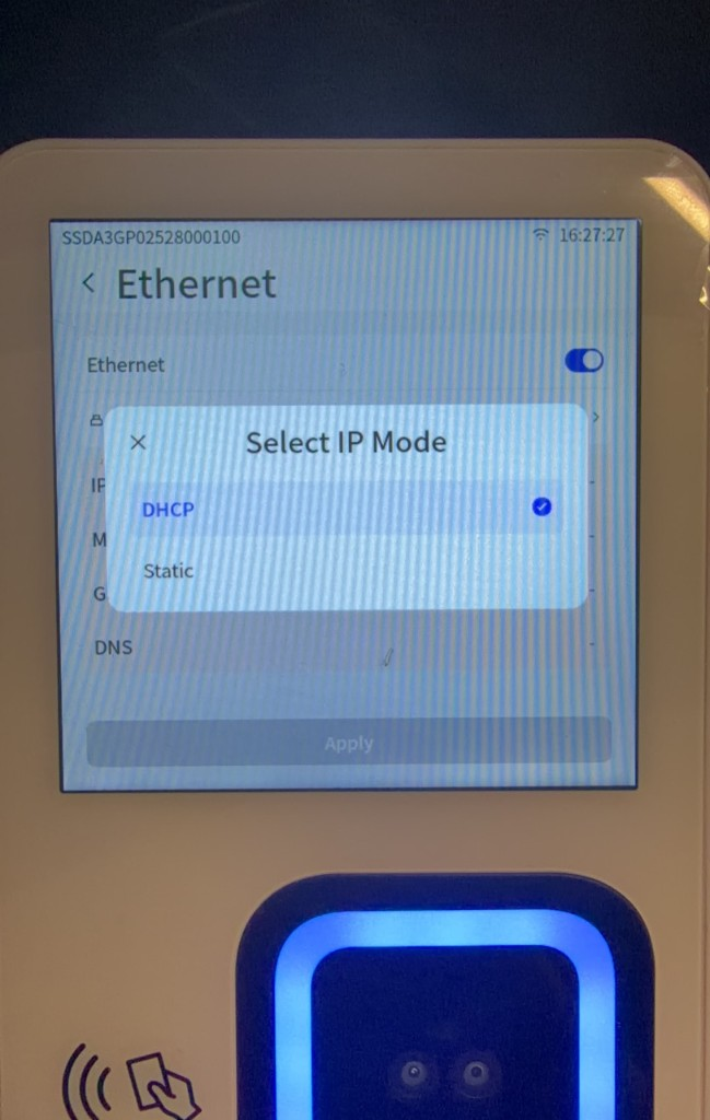
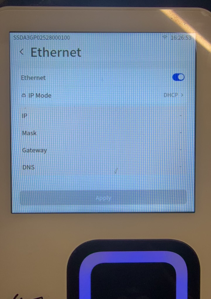
After you select DHCP, the device automatically obtains an IP address from the network.
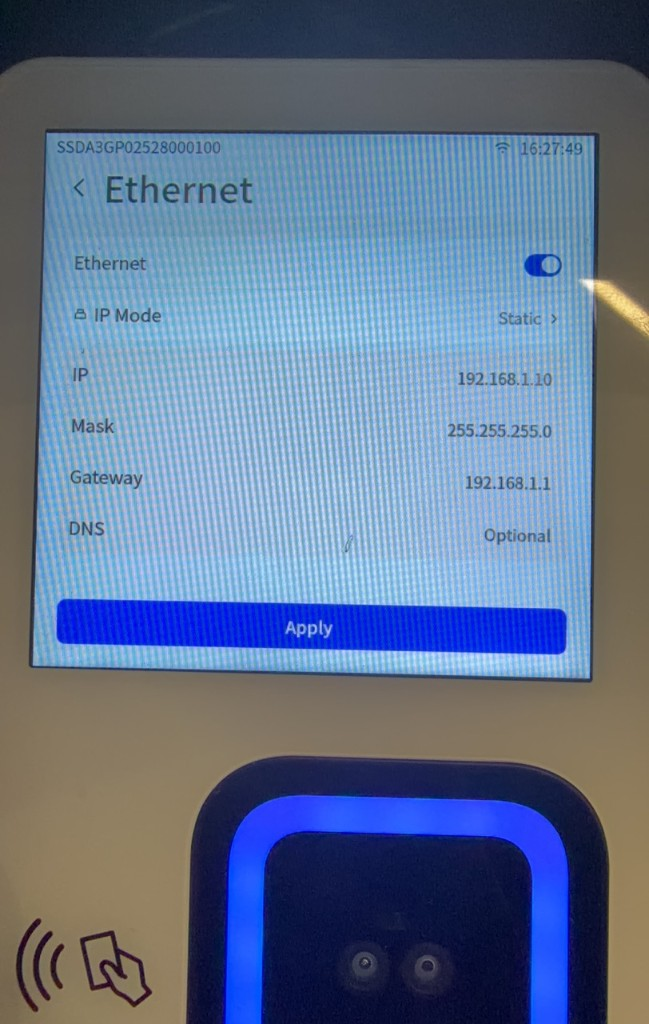
After you select Static, enter the IP address, gateway, DNS, and other information according to the on-site network plan, then tap Apply.
5.2.2.3 Connecting to WiFi
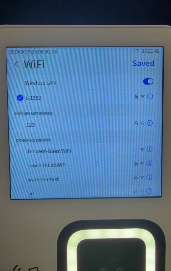
- Go to Setting > Network setting > WiFi.
- Turn on the wireless network switch.
- Select the target WiFi network from the list.
- If the network requires a password, enter it and connect.
- Wait for the device to connect.
Note
Wireless capabilities vary between M3 production batches. Some batches support only 2.4 GHz, while others support both 2.4 GHz and 5 GHz. If the device cannot find a 5 GHz network, use a 2.4 GHz network. Unsecured 5 GHz networks may have compatibility issues; use password-protected WiFi or switch to 2.4 GHz. A WiFi password containing a combination of letters and numbers is recommended.
To configure a static IP for the current WiFi network, tap the information button next to the connected network, select static IP mode on the network details page, and enter the IP address, subnet mask, gateway, and DNS according to the on-site network plan.
5.2.2.4 Managing Saved WiFi Networks
- Go to Setting > Network setting > WiFi.
- Tap Saved in the upper-right corner.
- View saved WiFi networks on the Saved networks page.
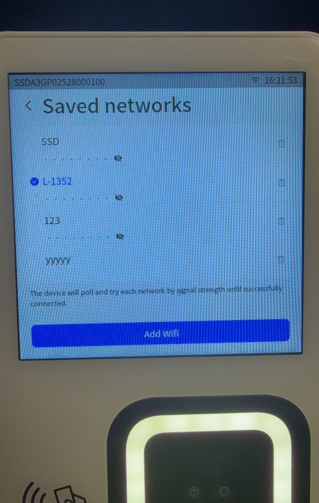
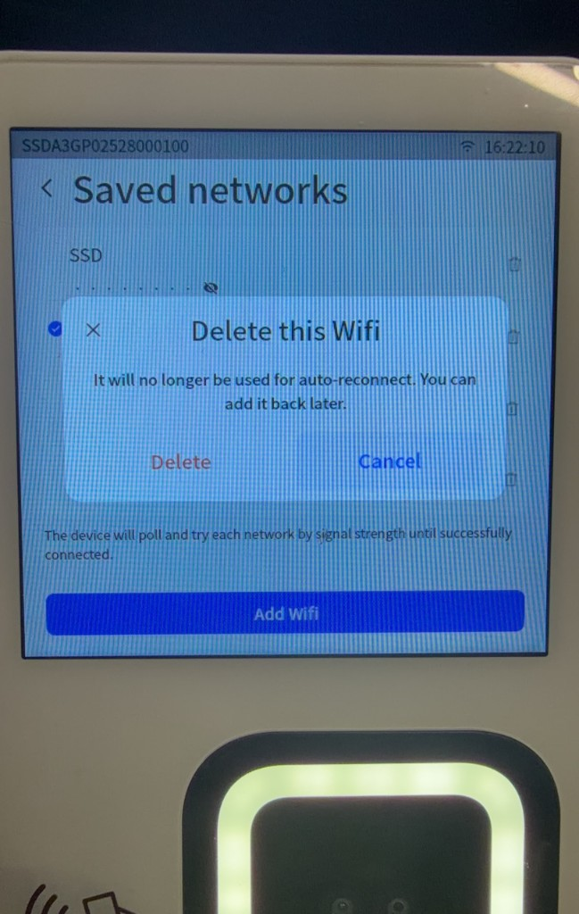
To delete a saved WiFi network, tap the delete button to its right.
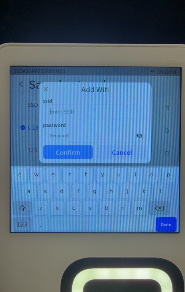
To add a WiFi network manually:
- On the Saved networks page, tap Add Wifi.
- Enter the WiFi name in ssid.
- Enter the WiFi password in password.
- Tap Confirm. To cancel, tap Cancel.
5.2.2.5 Connecting to a Hidden WiFi Network
- Go to Setting > Network setting > WiFi.
- Turn on the wireless network switch.
- Tap Other... in the WiFi list.
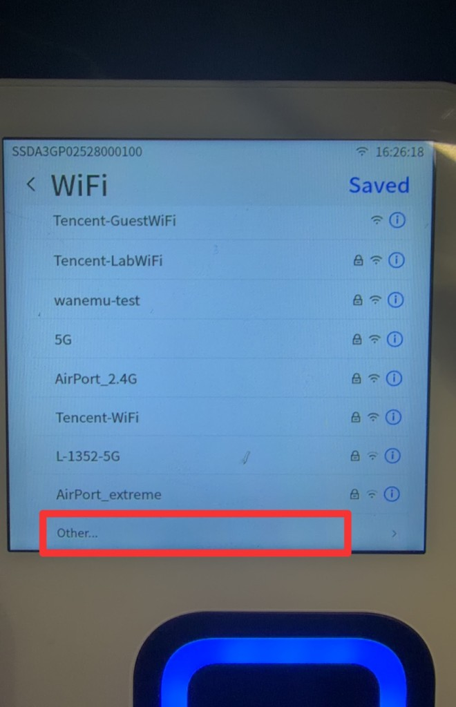
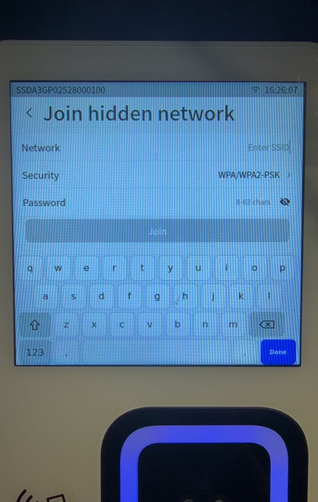
- On the Join hidden network page, tap Network and enter the hidden WiFi network's SSID.
- Tap Security and select the security type configured on the router.
- If the network requires a password, enter it in Password.
- Tap Join and wait for the device to connect.
Note
The SSID of a hidden WiFi network is case-sensitive. Enter it exactly as configured on the router.
5.2.2.6 Resetting Network Settings
Network Reset restores the device network settings to their defaults.
- Go to Setting > Network setting.
- Tap Network Reset.
- Tap Reset in the confirmation window.
- Reconfigure WiFi or Ethernet after the reset.
5.2.3 Completing Device Authorization
5.2.3.1 Authorization Preparation
Complete the following preparations before authorization:
- Confirm whether the device was permanently authorized at the factory. A permanently authorized device does not require on-site authorization.
- If the device has not been authorized or its authorization has expired, contact Sales or Technical Support for an authorization QR code.
- Online authorization is recommended by default. Confirm that the device can access the authorization service.
- Use offline authorization only as a fallback in exceptional cases.
- Print the authorization QR code on paper so that the device camera can scan it more easily.
When requesting an authorization QR code, provide the APP ID and specify the number of devices, authorization term, and whether online or offline authorization is required.
5.2.3.2 Online and Offline Authorization
| Authorization method | Network requirement during authorization | Use case |
|---|---|---|
| Online authorization | The device must be able to access the authorization service over the network. | Recommended by default for network-connected deployments. |
| Offline authorization | Authorization information is embedded in the QR code, so injecting it by scanning does not require a network. | A fallback for exceptional cases involving a completely offline standalone device. |
Description
An offline authorization QR code already contains the authorization information, so scanning and injecting it does not require a network. IoT activation, configuration synchronization, and online services still require network access.
For online authorization, identify the device's access path based on the deployment network:
- If the device can access the Internet, it can access the authorization service directly or complete authorization and authentication through the Backend Service Gateway.
- If the device is on a LAN with Internet access, it can reach the authorization service through the Backend Service Gateway on the same network.
- If neither the device nor the Backend Service Gateway can access the Internet, confirm that a working local authorization service has been deployed for the project. Otherwise, use offline authorization.
5.2.3.3 Scanning the Authorization QR Code
- On the Device authorization page, confirm that the current status is
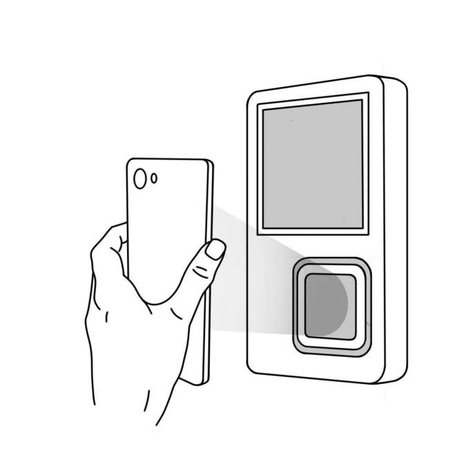
Unauthorized, then tap Scan the QR code. - Hold the authorization QR code approximately 10 cm from the palm scan camera module.
- Wait for the device to scan the code.
- After the scan succeeds, wait for the module to restart automatically.
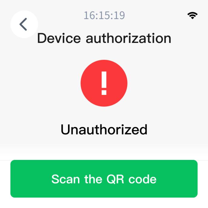
After the module restarts, the device displays the authorization result and validity period. If authorization fails, return to the authorization page and scan again. If it fails repeatedly, check the QR code, device time, and network, then contact After-Sales Support.
5.2.3.4 Viewing Authorization Status
After authorization succeeds, the device displays Authorization successful. You can subsequently go to Setting > Authorization, confirm that the status is Authorization Active, and view Authorization status, Validity period, APP ID, and Authorization path. When authorization expires, obtain a new authorization QR code and authorize the device again.
5.2.4 Registering a Device in the Admin Console
- Log in to the Admin Console and go to Device Management > Device List.
- Click Add Device.
- Enter a device name and the Device SN shown on the device label.
- Verify the information, then click Submit.
- Return to the device list and confirm that the device name and Device SN are correct.
The Device SN uniquely identifies the device and cannot be changed after entry. For batch device registration, see "3.1.1.1 Device Registration" in the Admin Console User Manual.
5.2.5 Activating the Device and Binding the Admin Console Environment
After registering the device, complete IoT activation to connect it to the current Admin Console environment.
- Confirm that the device has completed License authorization, is connected to the network, and has been registered in the current Admin Console.
- On the Device List page in the Admin Console, click Device Activation to generate an activation QR code.
- Scan the activation QR code with the M3.
- After activation succeeds, return to the device list and confirm that the device status has changed from not activated to online or offline.
For the complete activation QR code procedure, see "3.1.1.2 Device Activation and Environment Binding" in the Admin Console User Manual.
Note
Activation QR codes expire. If a code has expired, generate a new one in the Admin Console.
If activation fails, follow the applicable instruction:
This device is not registered: Confirm that the Device SN has been entered in the Admin Console.The QR code is not a valid activation code: Confirm that you scanned a device activation QR code.This activation code has expired: Generate a new activation QR code.- Network error or prolonged lack of response: Check the device network and try again.
5.2.6 Associating the Device with a Scene
After activation, associate the device with the scene where it will be used.
- Log in to the Admin Console and go to Verification > Scene Management.
- Select the target scene group.
- Locate the target scene and click Edit. If it does not exist, click Add Scene.
- Select the M3 under Associated device.
- Select a recognition strategy under Scene Strategy.
- To restrict users and access times, enable Verification Rule and select a verification rule.
- Click Submit.
A device cannot be associated with multiple scenes at the same time. To change its scene, first remove it from Associated device in the original scene, then add it to the new scene.
For instructions on creating and editing scenes, see "3.2.2 Scene Management" in the Admin Console User Manual. For rules covering authorized users, valid dates, blocked dates, and time periods, see "3.4 Verification Rules."
5.3 Basic Device Settings
This section describes language, volume, time, password, device information, and restart settings.
5.3.1 Opening the Setting Page
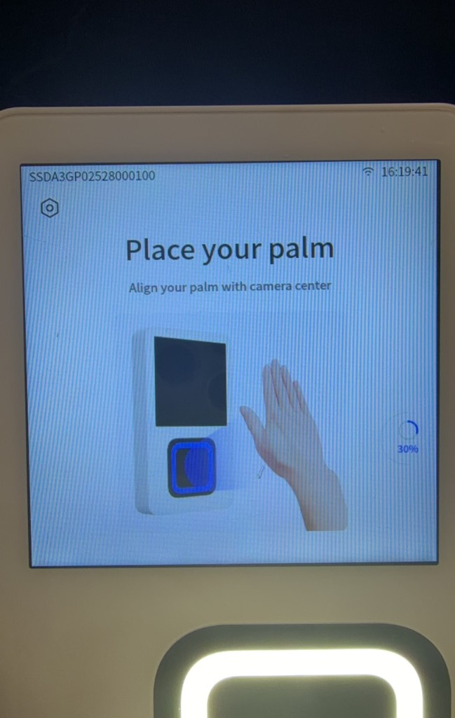
- Tap the settings button in the upper-left corner of the device home page.
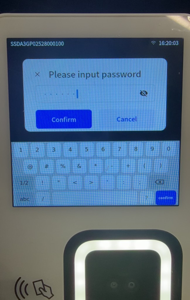
- Enter the device settings password in the Please input password window. The initial password is
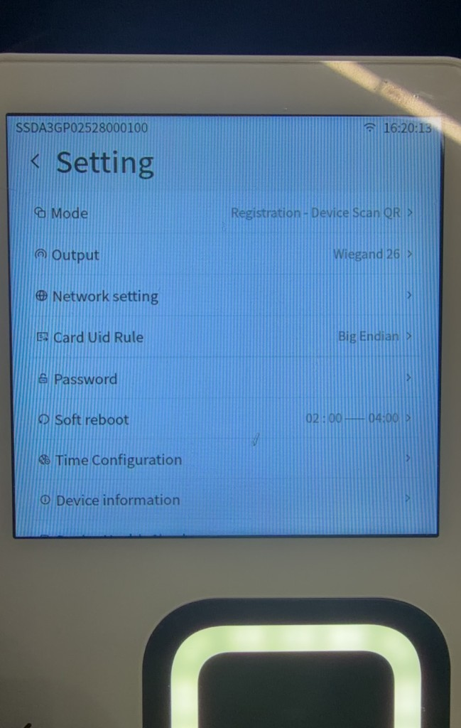
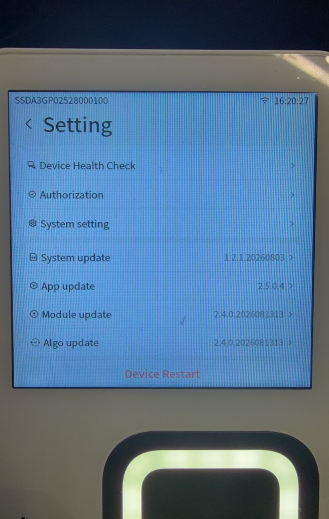
000000. - Tap Confirm to open the Setting page. To cancel, tap Cancel.
5.3.2 Setting the Device Language
- Go to Setting > System setting.
- Tap Language.
- Select the desired language.
A selection indicator appears next to the current language.
5.3.3 Setting the Device Volume
- Go to Setting > System setting.
- Locate the volume slider.
- Drag the slider left or right to adjust the volume of voice prompts and notification sounds.
5.3.4 Viewing and Synchronizing Device Time
- Go to Setting > Time Configuration.
- View Time Zone and Current Time.
- To synchronize the time again, tap Resync Time.
- After synchronization succeeds, confirm that the device time is correct.
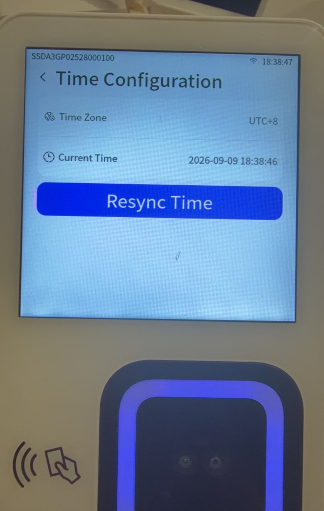
You can only view and resynchronize the time on the device; you cannot change the time zone directly. After the device is activated for the current tenant, its time zone is synchronized with the time zone configured in the Admin Console. A super administrator manages that setting under System > System Settings > Timezone Settings.
5.3.5 Changing the Device Settings Password
- Go to Setting.
- Tap Password.
- Enter a new password.
- Tap Confirm.
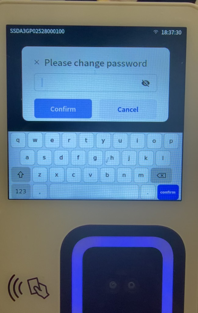
Note
Store the new password securely. If you forget it, contact After-Sales Support to reset it.
5.3.6 Viewing Device Information
Go to Setting > Device information to view the current tenant, scene, service endpoint, Device SN, IP address, Ethernet MAC, WLAN MAC, and other information.
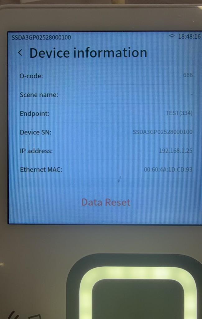
To view component versions, return to the Setting page and scroll down:
| Entry | Information displayed |
|---|---|
| System update | System version |
| App update | Application version |
| Module update | Module version |
| Algo update | Algorithm version |
5.3.7 Restarting the Device
The M3 supports scheduled automatic restarts, restarts from the Setting page, and restarts using the concealed reset button.
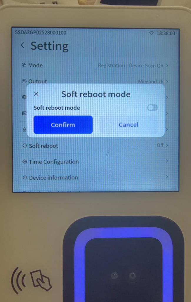
Configure automatic restart
- Go to Setting > Soft reboot.
- Enable Soft reboot mode.
- Select a start time under Select start time.
- Tap Confirm.
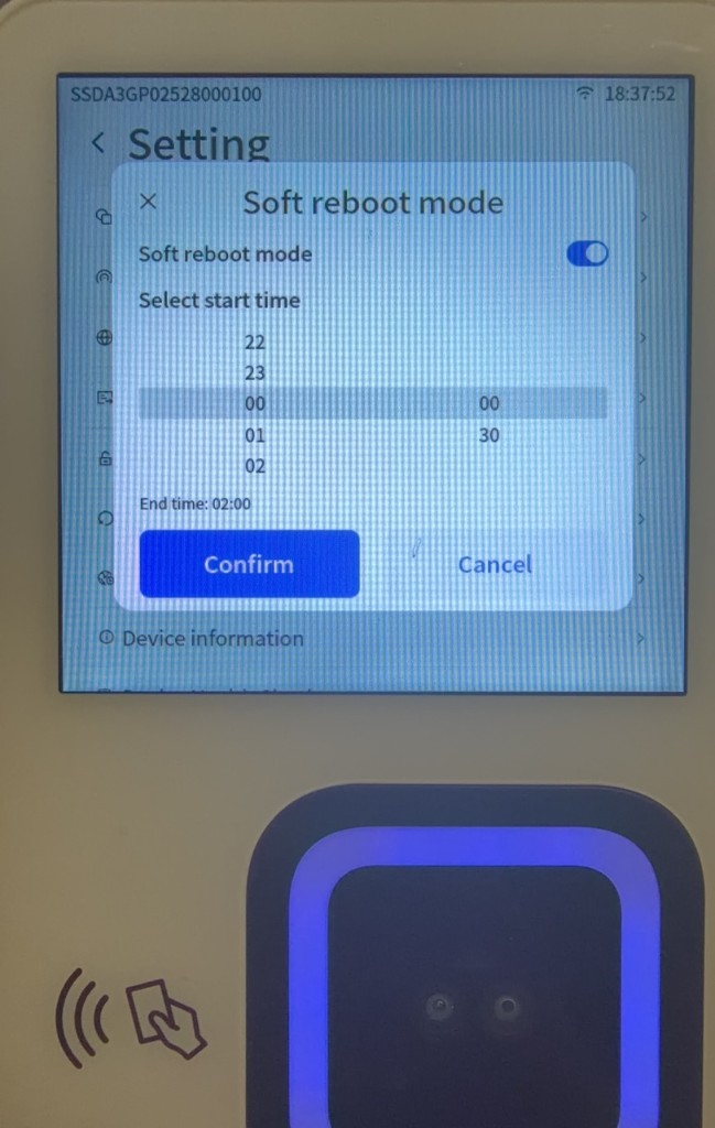
Each day, the device automatically restarts within the configured time range when no one is performing a palm scan. Enable this feature for devices that run continuously for long periods.
The device selects an idle period within one hour after the chosen start time to restart, minimizing disruption to on-site operations.
To disable automatic restart, turn off Soft reboot mode, then tap Confirm.
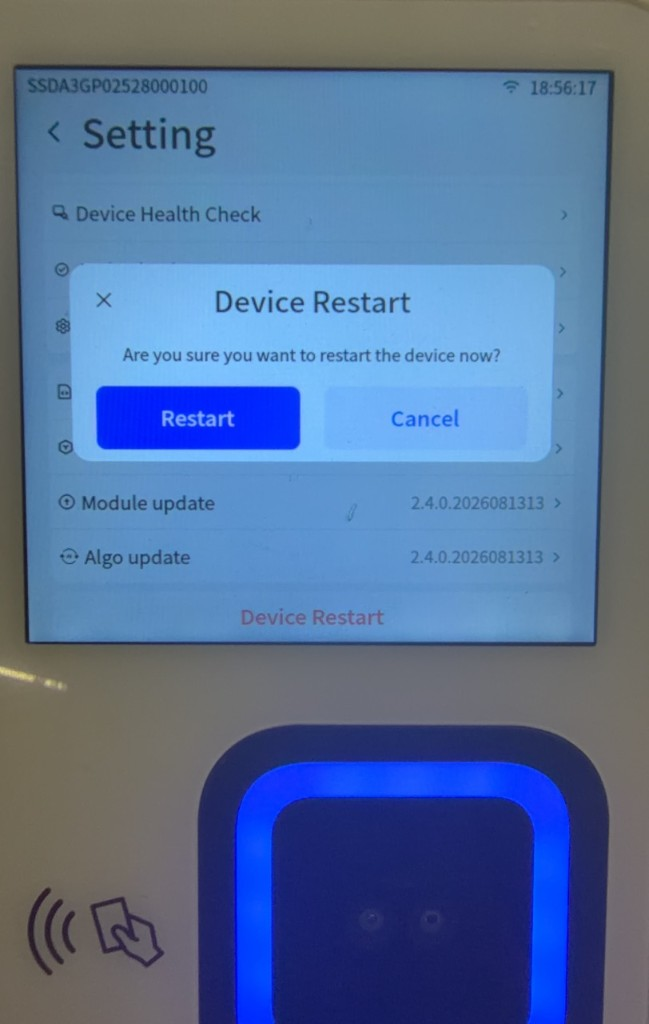
Restart from the Setting page
- Open the Setting page and scroll to the bottom.
- Tap Device Restart.
- Tap Restart in the confirmation window and wait for the device to restart.
5.4 Service Activation and Palm Scan
5.4.1 Switching Device Registration and Recognition Modes
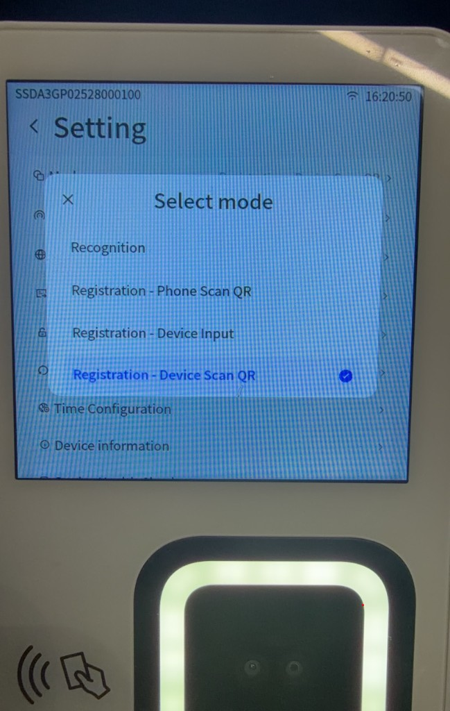
The M3 supports four registration methods: phone scan QR, device input, device scan QR, and Mobile Palm Registration. Select mode on the device currently provides only the following four options:
- Recognition
- Registration - Phone Scan QR
- Registration - Device Input
- Registration - Device Scan QR
Mobile Palm Registration is not a separate device registration mode. The user first preregisters a palm through a mobile App or the Mobile Palm Registration H5 page, then activates it with the first palm scan in Recognition mode.
| Registration method | Description | Device mode |
|---|---|---|
| Phone Scan QR Registration | The device captures the palm first. The user scans the QR code displayed by the device with a phone and enters user information. | Registration - Phone Scan QR |
| Device Input Registration | The device captures the palm first, after which the user information is entered on the device. | Registration - Device Input |
| Device Scan QR Registration | The user first generates a QR code on the H5 registration page. After capturing the palm, the device scans that QR code. | Registration - Device Scan QR |
| Mobile Palm Registration | The user preregisters a palm through a mobile App or the Mobile Palm Registration H5 page, then activates it with the first palm scan on the device. | Recognition |
To switch modes:
- Go to Setting.
- Tap Mode.
- Select the target mode under Select mode.
Before using a registration feature, confirm that the device has been authorized, connected to the network, activated through IoT, and associated with a scene. In a closed scene, an administrator must first create the user in the Admin Console. The User ID and Username entered during registration must match the Admin Console records. For instructions, see "3.5.1 Create User" in the Admin Console User Manual.
The administrator must also edit the current tenant under System > Tenant Management and enable the registration methods required by the project. For complete tenant registration settings, see "3.9.1 Create Tenant" and "3.9.3 Edit Tenant" in the Admin Console User Manual.
5.4.2 Phone Scan QR Registration
- Under Setting > Mode, select Registration - Phone Scan QR.
- Hold an unregistered palm over the palm scan camera module and follow the device prompts to complete capture.
- After the palm is captured, the device displays a registration QR code.
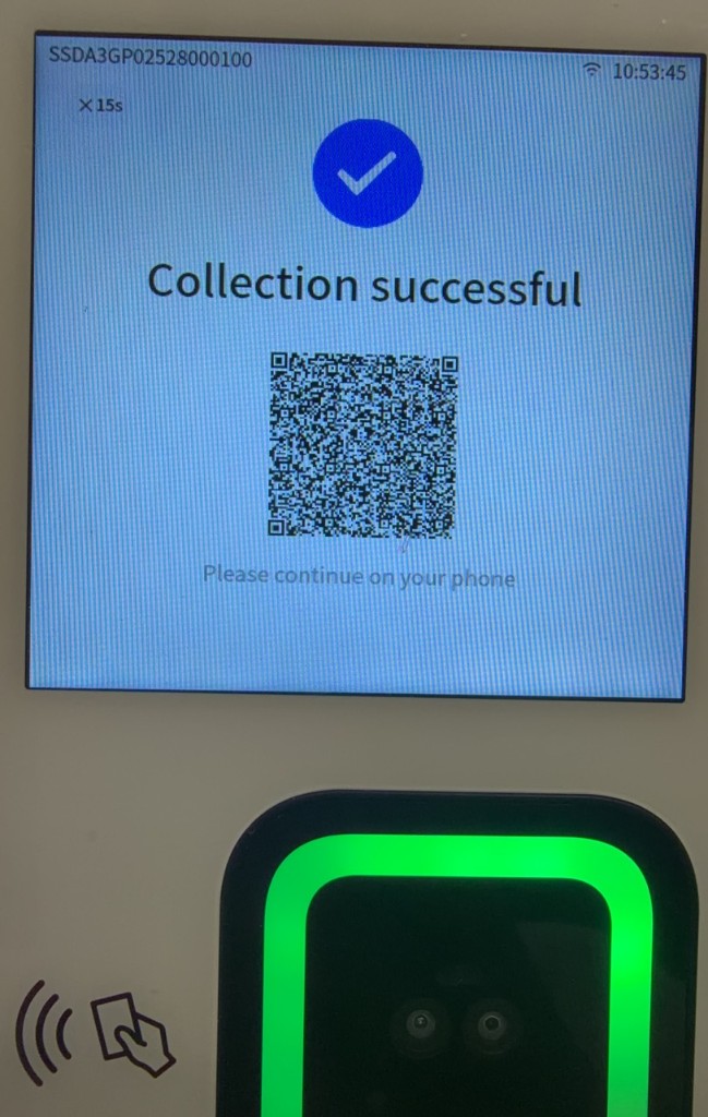
- Scan the QR code displayed by the device with a phone.
- Enter User ID, Username, and other information on the phone registration page.
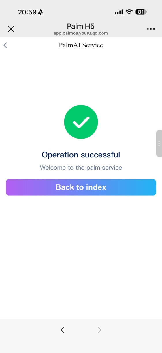
- Tap Submit.
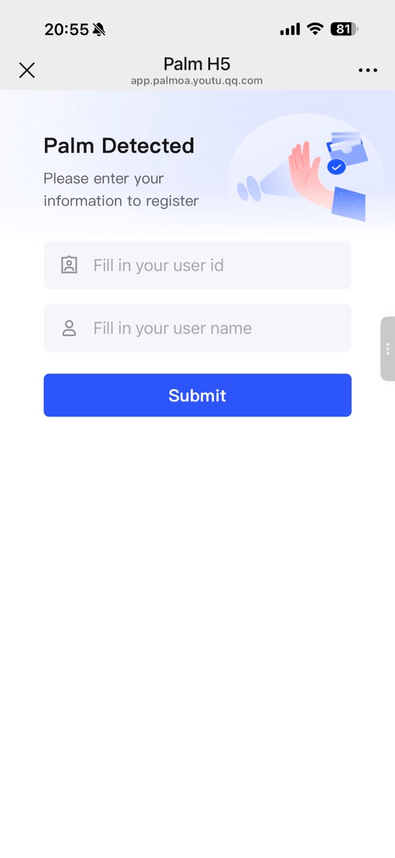
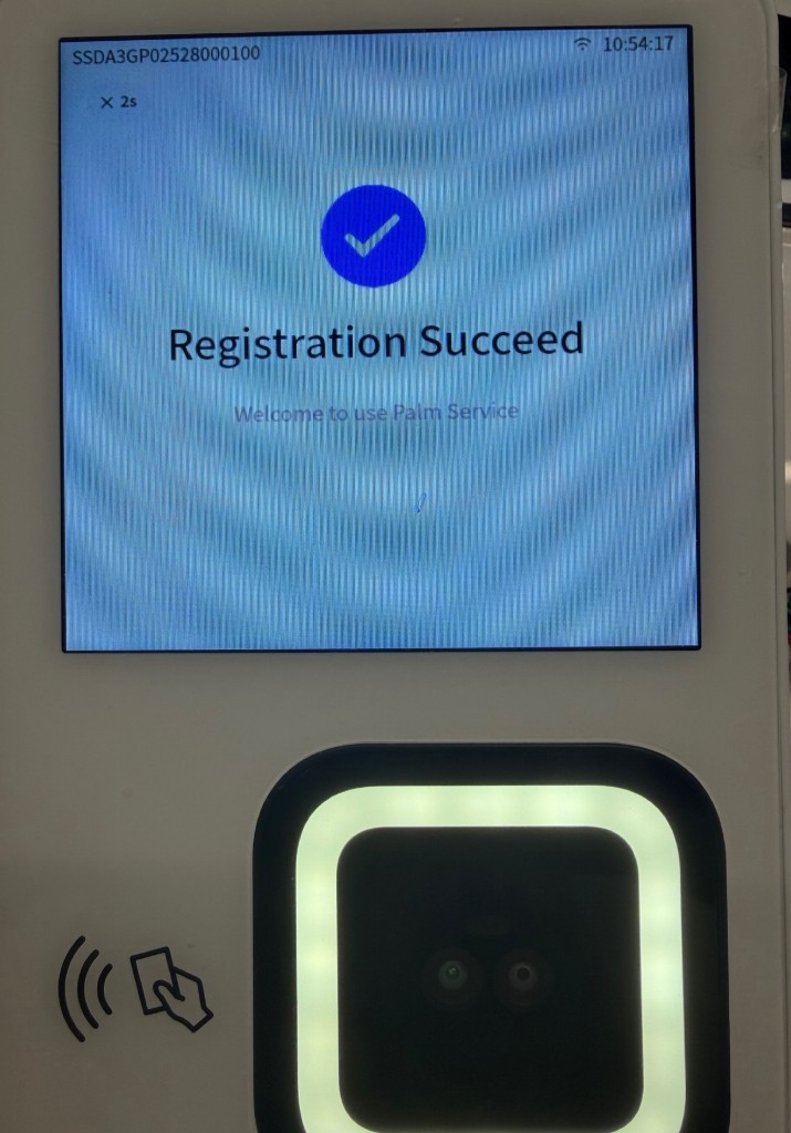
- Confirm that the phone page reports a successful submission and the device reports successful registration.
5.4.3 Device Input Registration
- Under Setting > Mode, select Registration - Device Input.
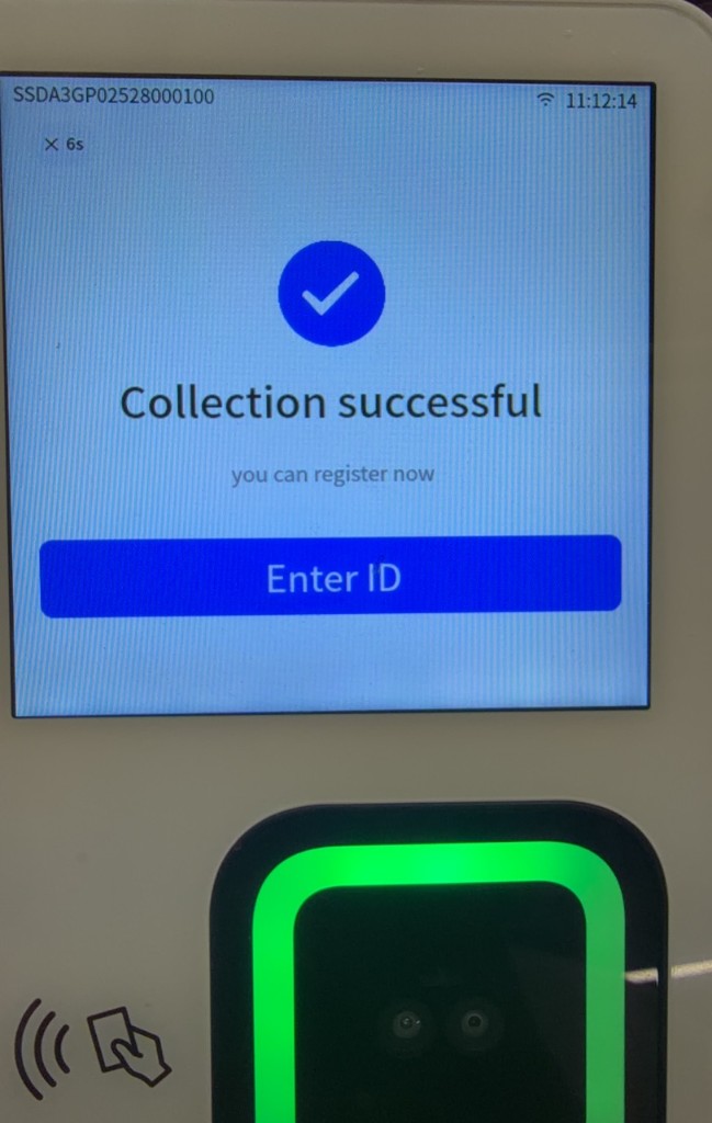
- Hold an unregistered palm over the palm scan camera module and follow the prompts to complete capture.
-
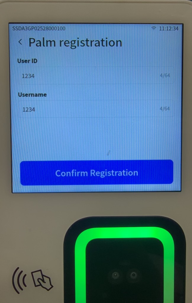
After the palm is captured, tap Enter ID.
-
Enter User ID and Username.
-
Tap Confirm.
-
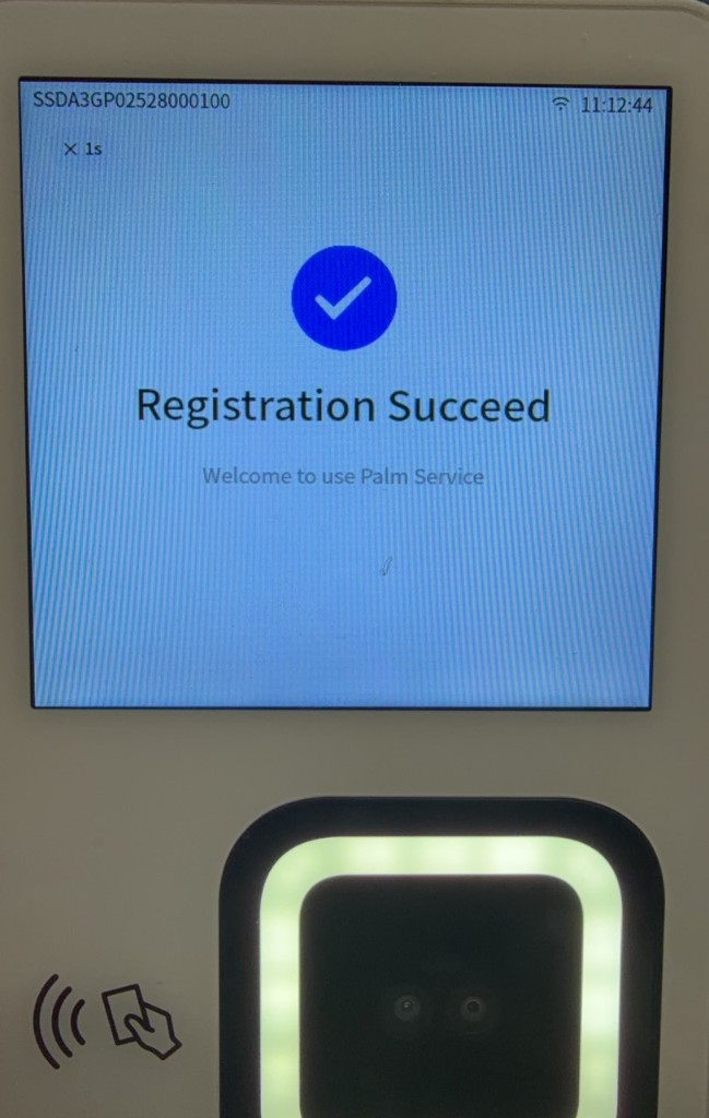
Confirm that the device reports successful registration.
5.4.4 Device Scan QR Registration
For the complete procedure for generating a registration QR code on the H5 page, see "4.8 Device Scan QR Registration" in the Mobile Application User Manual.
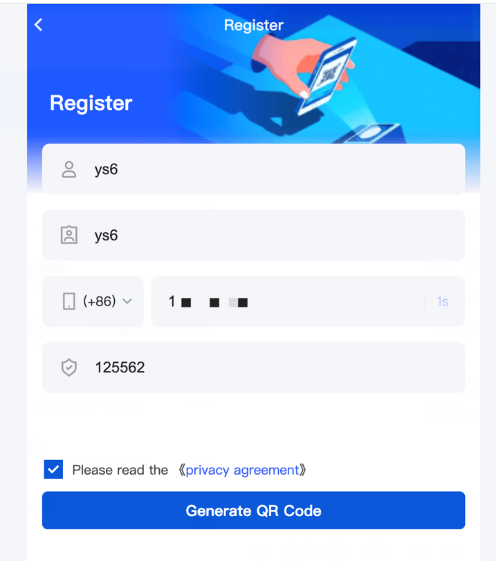
- Open the H5 registration page provided for the current project.
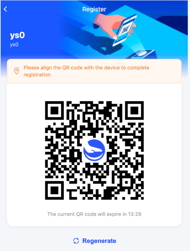
- Enter User ID, Username, mobile number, and other information to generate a registration QR code.
- Under Setting > Mode on the device, select Registration - Device Scan QR.
- Hold an unregistered palm over the palm scan camera module and follow the prompts to complete capture.
- When the device opens the QR code scan page, hold the H5 registration QR code in front of the camera.
- After the scan succeeds, verify the user information displayed by the device.
- Tap the confirm button to complete registration.
Note
A registration QR code is valid for 15 minutes. If it expires, generate a new one on the H5 registration page. If scanning fails, clean the camera and increase the clarity of the phone display before trying again.
5.4.5 Mobile Palm Registration
With Mobile Palm Registration, a user preregisters a palm using a phone camera through a mobile App or the Mobile Palm Registration H5 page, then activates the palm by performing the first palm scan on the M3. After mobile preregistration, the palm cannot yet be used for normal verification.
Prerequisites
- Mobile Palm Registration has been enabled for the current tenant in the Admin Console.
- In an open scene, an administrator does not need to create the user in advance. The system creates the user automatically when registration information is submitted in the App.
- In a closed scene, an administrator has created the user in the Admin Console. The user information entered in the App must match the Admin Console records.
- The user has installed a mobile App that supports Mobile Palm Registration or can access the Mobile Palm Registration H5 page.
This section uses the PalmMa demo App connected to the Indonesia production environment to illustrate Mobile Palm Registration. You can also experience the same process through the Mobile Palm Registration H5 page. These entry points are provided only for feature evaluation and integration reference. To implement Mobile Palm Registration in a customer service, integrate the Mobile Palm Registration App SDK or H5 SDK by following the Palm Developer documentation and develop the required features. Pages, processes, and environment settings for a production project depend on the customer's actual integration.
For the complete procedures for mobile preregistration, viewing palm status, and managing two palms, see "4.5 Mobile Palm Registration and Palm Management" in the Mobile Application User Manual.
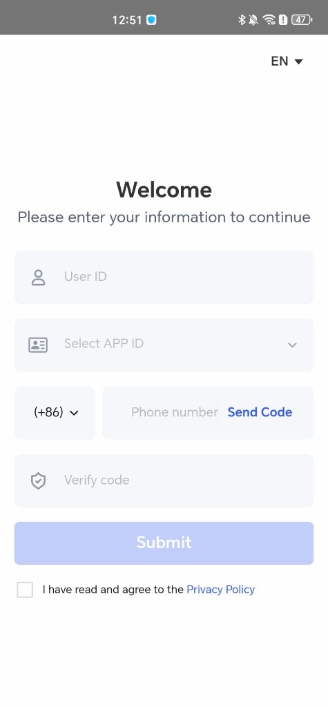
Log in to the PalmMa demo App or Air Enrollment H5
- Open the PalmMa demo App or the Air Enrollment H5 page, then enter User ID.
- Select a tenant name. Available tenants include open tenants and closed tenants that already contain this User ID. You can check whether a tenant uses an open scene or a closed scene in PalmAI Admin Web under System Management > Tenant Management.
- Read and accept the privacy agreement, then tap Submit to open the feature home page.
Preregister the first palm
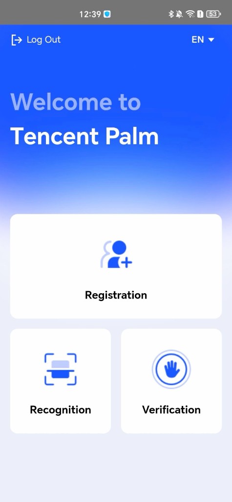
- Tap Registration on the feature home page.
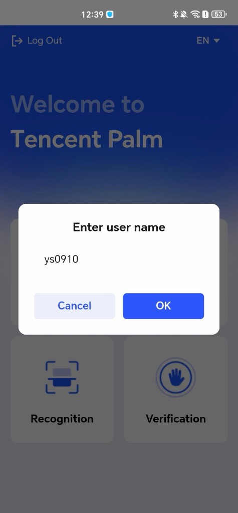
- In an open scene, enter a username in the Enter user name dialog during the first registration, then tap OK. The system creates the user and opens the Palm Registration page. In a closed scene, the system uses the user information already created in the Admin Console.
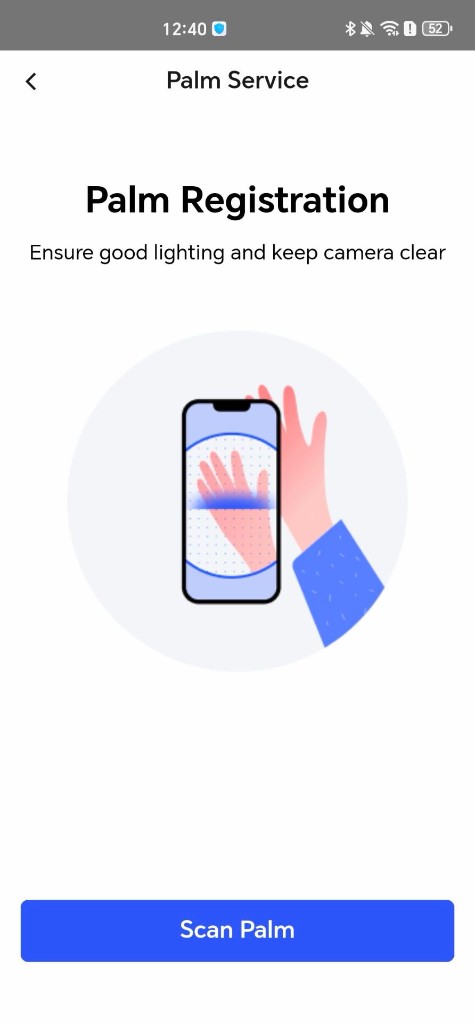
- Ensure that the area is well lit and the camera is clean, then tap Scan Palm.
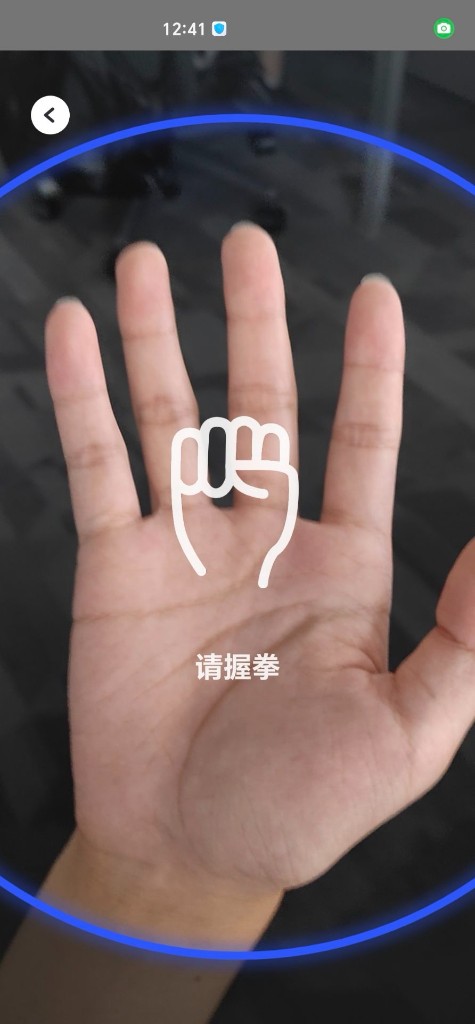
- Scan the palm with the phone's rear camera and follow the on-screen prompts to open the hand, make a fist, and complete the other required actions in sequence.

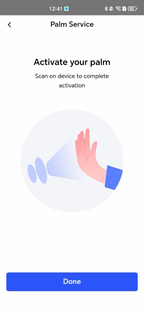
- When the page displays Activate your palm, tap Done.
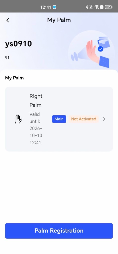
- Open the My Palm page and confirm that the preregistered palm is marked
Not Activated.
Activate the palm on the M3
- Confirm that the M3 has been authorized, connected to the network, activated in the Admin Console environment, and associated with a scene.
- Under Setting > Mode on the M3, select Recognition.
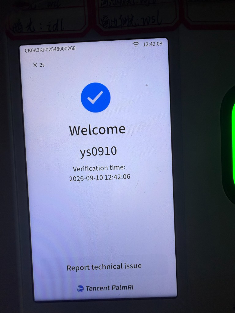
- Perform the first palm scan with the preregistered palm and wait for the device to display the palm scan success page.
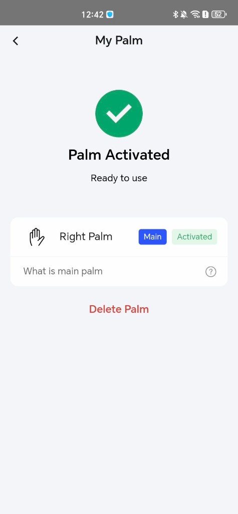
- Return to the PalmMa demo App, open My Palm, and tap the corresponding palm. Confirm that its status is now
Activated. The first palm activated is markedMain.
Preregister and activate the second palm
- Open My Palm and tap Palm Registration or the position for the palm that has not been registered.
- Follow the preceding steps to preregister the other palm.
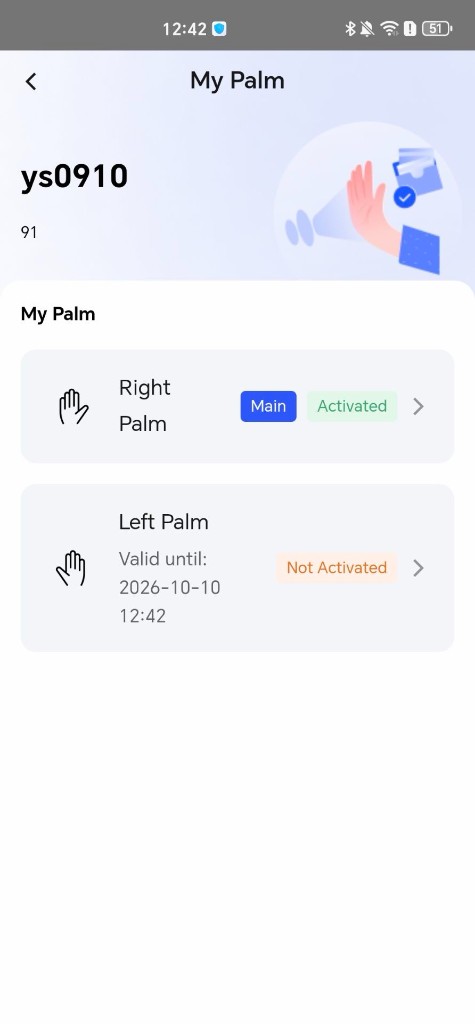
- Confirm that the first palm is marked
Activatedand the newly preregistered palm is markedNot Activated.
- Switch the M3 to Recognition, then perform the first palm scan with the second palm to activate it.
- Return to My Palm and confirm that both palms are marked
Activated. The first palm activated is the Primary Palm, and the palm activated later is the Secondary Palm.
If the device reports that the palm is not registered, confirm that mobile preregistration succeeded. If it reports no access permission or an invalid access time, ask an administrator to check the scene and verification rule. If it reports a network error, restore the network and perform another palm scan.
5.4.6 Primary and Secondary Palm Rules
The same user can register both the left and right palms. To register the second palm, use the same registration method and submit the same user's information.
- The first palm activated is marked as the Primary Palm,
Primary. - The other palm, registered and activated later, is marked as the Secondary Palm,
Secondary. - Either the left or right palm can be the Primary Palm. Primary and Secondary Palm status depends on activation order.
- If a palm in the same direction has already been registered, the system rejects duplicate registration.
- When Dual Palm Registration is enabled, each user can consume up to two Palm Database Quota units.
5.4.7 Performing Daily Palm Scan Verification
Prerequisites
- The device has been authorized, connected to the network, activated through IoT, and associated with a scene.
- The scene strategy, verification rule, and user access permissions have taken effect.
- The user has completed Palm Registration. A Mobile Palm Registration user has completed initial activation on the device.
- When access control output is used, the user has a Physical Card Number, and the device output matches the controller configuration.
Procedure
- Go to Setting > Mode.
- Under Select mode, select Recognition.
- Return to the device home page.
- Extend a registered palm naturally with its center facing the center of the palm scan camera module.
- Keep the palm approximately 5–12 cm from the device.
- Wait for the device to complete capture and verification.
- View the verification result. If Additional Verification is triggered, follow the on-screen prompts to complete the additional identity check.
After successful verification, the device displays the success page and turns on the green light. When a user with two registered palms verifies with either activated palm, the device can display Left Hand or Right Hand.
The NFC card reader area can be used to swipe an access card, but its capability depends on the on-site access control configuration. The presence of the NFC area does not mean that the device provides a separate card registration process.
5.4.8 Configuring High-Similarity Deduplication During Registration
High-similarity deduplication determines during registration whether the current palm is highly similar to an existing palm. This feature affects only Palm Registration results and is separate from Additional Verification after a palm scan.
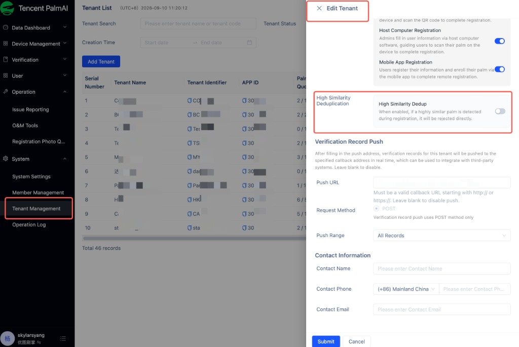
An administrator configures this feature in the Admin Console:
- Go to System > Tenant Management.
- Locate the current tenant and click Edit.
- Locate High Similarity Deduplication and configure the High Similarity Dedup switch.
- Click Submit to save the setting.
The switch has the following effects:
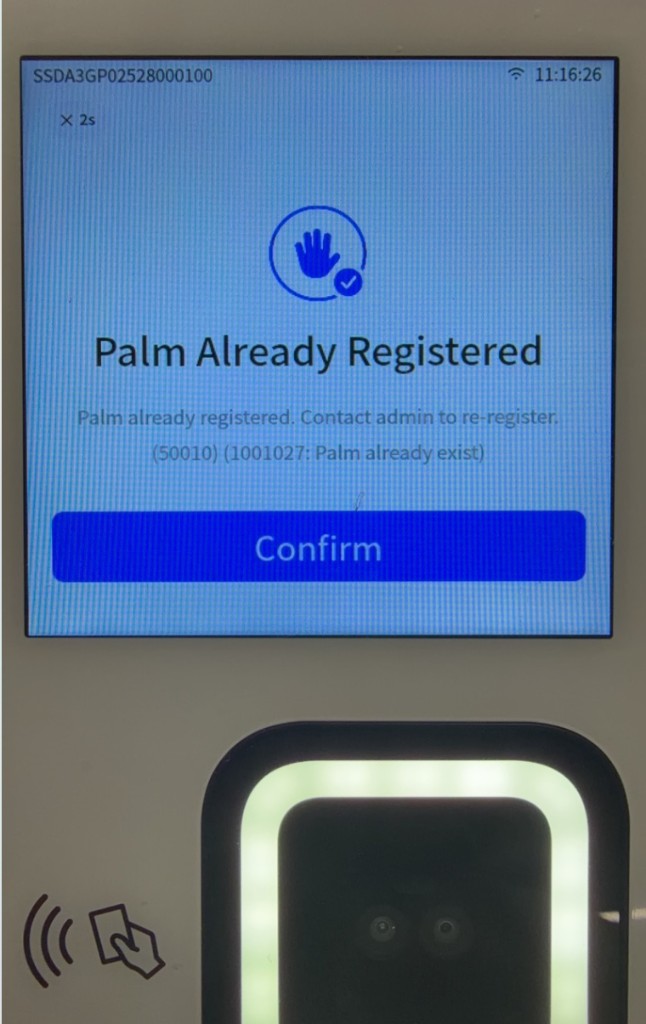
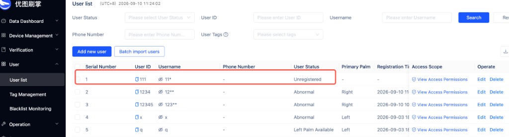
High Similarity Dedup enabled
If the system detects a highly similar palm during Palm Registration, it rejects the registration. The M3 displays Palm Already Registered, and the User Status in the Admin Console is Unregistered.
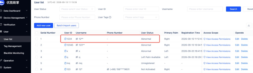
High Similarity Dedup disabled
When a highly similar palm is registered, the M3 still reports successful registration, but the User Status in the Admin Console is Abnormal.
For complete tenant configuration procedures, see "3.9.1 Create Tenant" and "3.9.3 Edit Tenant" in the Admin Console User Manual.
5.4.9 Using Additional Verification
Additional Verification is an additional identity check performed after a palm scan. The device supports three methods: the last four digits of a mobile number, a custom numeric field, and device QR code scanning.
An administrator edits the tenant under System > Tenant Management and configures Verification Method under Verification Configuration. For the complete tenant-level Additional Verification procedure, see "3.9.4 Tenant-Level Additional Verification Configuration" in the Admin Console User Manual.
Verification Method supports:
- Last 4 Digits of Phone Number
- Custom Field
- Device QR Code Scan
When Custom Field is selected, specify the user field to be used for Additional Verification. When Device QR Code Scan is selected, you can configure QR Code Expiration.
5.4.9.1 Additional Verification Using the Last Four Digits of a Mobile Number
- The administrator confirms that a mobile number is present in the user's information.
- The user completes a palm scan.
- When the device displays the numeric input page, enter the last four digits of the mobile number.
- Submit the information and wait for the system to complete the additional identity check.
5.4.9.2 Additional Verification Using a Custom Numeric Field
A custom numeric field supports 4–8 digits.
- In the tenant settings, the administrator specifies the active field and maintains a corresponding field value for each user.
- The user completes a palm scan.
- When the device displays the numeric input page, enter the corresponding number.
- Tap the confirm button.
- View the Additional Verification result. If verification fails, verify the user's field value and try again.
5.4.9.3 Additional Verification by Device QR Code Scan
For the complete procedure for generating an authentication QR code on the H5 page, see "4.9 Additional Verification by Device QR Code Scan" in the Mobile Application User Manual.
- The user completes a palm scan.
- The device prompts the user to present an authentication QR code and activates the camera.
- The user opens the H5 Additional Verification page provided for the current project and follows the page instructions to generate an authentication QR code.
- Hold the authentication QR code in front of the device camera.
- The device completes Additional Verification after scanning the code successfully.
Note
The validity period of an authentication QR code is configured in the Admin Console and defaults to 60 seconds. If either the QR code or the device's scan wait period expires, perform another palm scan and generate a new authentication QR code.
5.4.10 Configuring Access Control Output and Opening the Door
The M3 can output a door-open signal to an access controller through a relay or Wiegand. Before using Wiegand, an administrator must assign the user a Physical Card Number. This can be an actual card number or a virtual number assigned by the service.
5.4.10.1 Assigning a Physical Card Number to a User
- Log in to the Admin Console and go to User Management > User List.
- Locate the target user and click Edit.
- Enter the Physical Card Number in Physical card number.
- Save the user information.
For creating an individual user and entering a Physical Card Number, see "3.5.1 Create User" in the Admin Console User Manual. To modify an existing user, see "3.5.2 Edit User."
Note
M3 access control recognition requires a Physical Card Number for the user. Without one, a palm may register successfully, but a subsequent palm scan may report that no Physical Card Number was read and fail to open the door.
5.4.10.2 Selecting an Output Method
- Go to Setting.
- Tap Output.
- Select an output method under Access Mode. For Wiegand, select the format that matches the access controller:
- Relay
- Wiegand 26bit
- Wiegand 32bit
- Wiegand 34bit
- Wiegand -26bit
- Wiegand -32bit
- Wiegand 64bit
- Wiegand -64bit
- Wiegand 66bit
- Wiegand -66bit
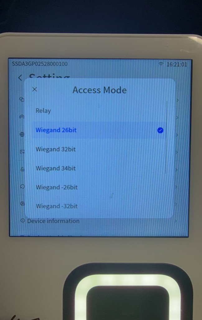
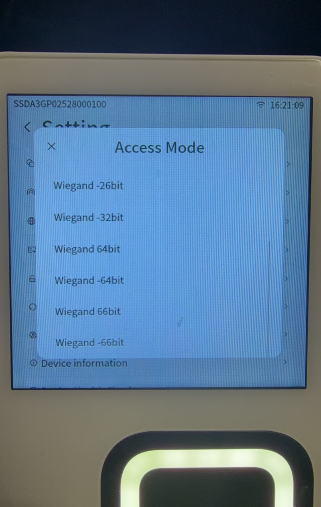
When Relay is selected, confirm that the relay's NO, NC, and COM wiring matches the door lock type. When Wiegand is selected, confirm that D0, D1, and GND are wired correctly.
5.4.10.3 Setting Physical Card Number Byte Order
- Go to Setting.
- Tap Card Uid Rule.
- Under Select Endian, select:
- Big Endian
- Little Endian
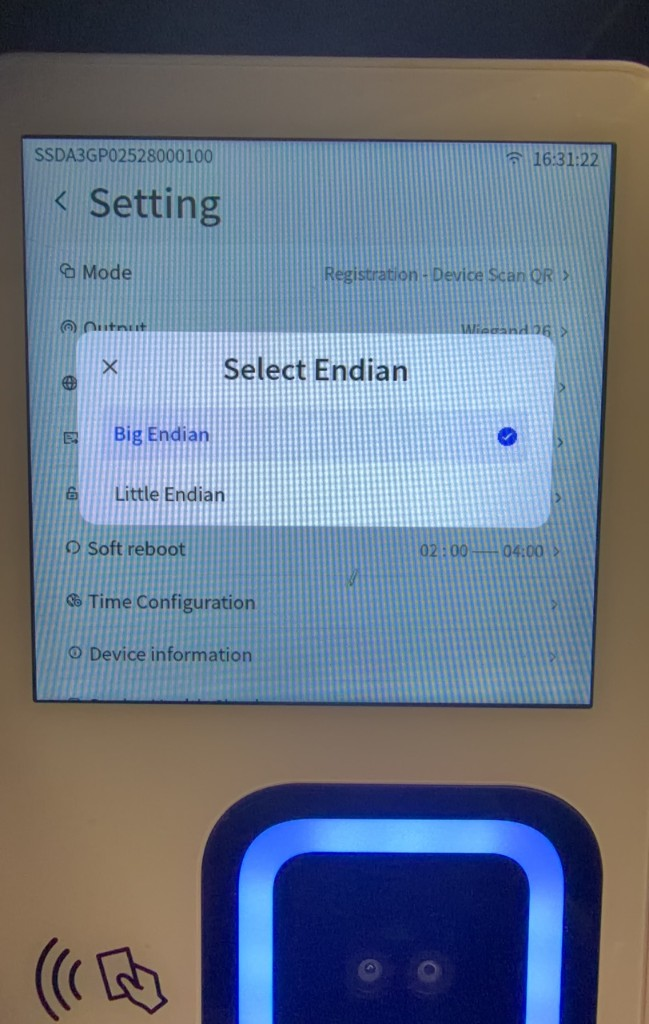
The controller parses the same Physical Card Number differently under different byte orders. The byte order must match the access controller's card-number parsing rule.
5.4.10.4 Checking the Wiegand Bit Length
After conversion to binary, the decimal Physical Card Number entered in the Admin Console must not exceed the data-bit capacity of the selected Wiegand format:
| Output format | Maximum Physical Card Number bit length |
|---|---|
| Wiegand 26bit | 24 bits |
| Wiegand -26bit | 26 bits |
| Wiegand 32bit | 30 bits |
| Wiegand -32bit | 32 bits |
| Wiegand 34bit | 32 bits |
When using a 64-bit or 66-bit format, also confirm that the controller supports the format and that the card number does not exceed its data capacity.
After completing the settings, test with a registered user who has access permission. Check all of the following:
- The device reports successful verification.
- The access controller receives the correct card number.
- The controller parses the bit length and byte order correctly.
- The turnstile or door lock operates as configured.
5.4.10.5 Opening the Door with a Card or Palm Scan
After configuring the access control wiring, user Physical Card Number, and access permissions, verify door opening with an access card or registered palm:
- Hold the access card near the NFC card reader area, or hold a registered palm over the palm scan camera module.
- Wait for the device to read the card number or complete palm scan verification.
- Confirm that the device outputs a relay or Wiegand signal according to the current Access Mode.
- Confirm that the access controller receives the signal and opens the door lock or turnstile.
Card availability and card-number permissions depend on the on-site access control configuration. The M3 does not provide a separate card registration process.
5.4.11 Reporting and Viewing Verification Records
After the device is online and associated with a scene, it uploads verification results to the Palm Application Platform.
- Log in to the Admin Console and go to Verification > Verification Records.
- Filter records by time range, scene, User ID, Username, verification status, or source.
- Click Search.
- View the verification time, verification status, user, scene, verification method, and Device SN.
- To save records, export the verification records within the current permission scope.
Device reporting of Verification Records and platform pushes to a third-party system are separate processes. Third-party pushes are configured under Verification Record Push for the tenant. For complete field descriptions, see "3.9.1 Create Tenant" and "3.9.3 Edit Tenant" in the Admin Console User Manual.
5.5 Device Configuration and Routine Maintenance
5.5.1 Configuring and Distributing a Custom UI
An administrator can configure the device home page, verification success page, verification failure page, and result countdown in the Admin Console, then distribute the configuration by scene or Device SN.
- By Scene: Applies to devices in the selected scene.
- By Device SN: Applies only to the selected device.
The device checks for Theme Package changes every 10 minutes. When it detects an update, it downloads the package in the background and prompts the user to apply it after the download completes. If no template is configured or the current template has been deleted, the device uses the system default style. The device cannot obtain updates while it is offline or powered off, but will retrieve them during a subsequent check after network connectivity is restored.
After the Theme Package is downloaded, the device indicates that it will apply the new theme automatically in 10 seconds. To apply it immediately, tap the button on the page for immediate use. If the current theme template is deleted, the device automatically restores the system default style.
For the complete procedure, see "3.1.2 Device Configuration" in the Admin Console User Manual.
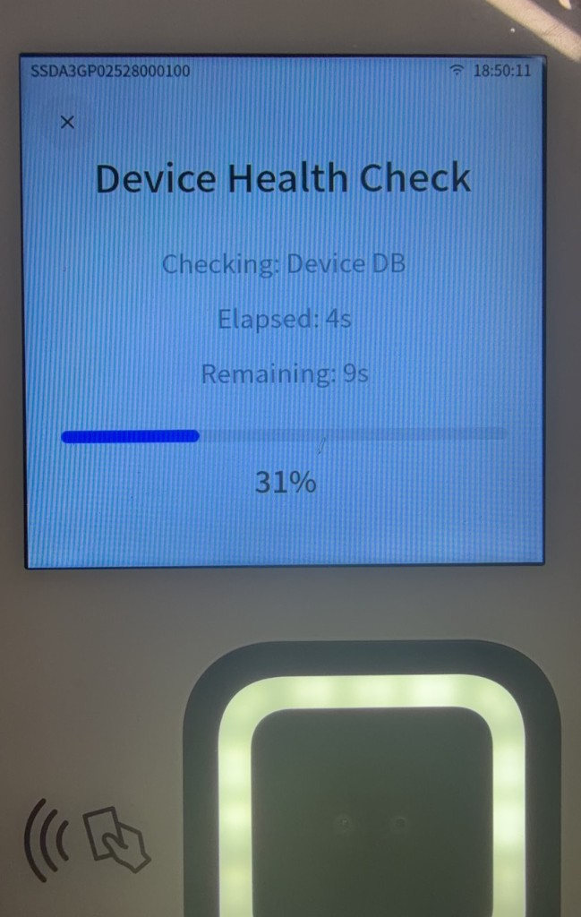
5.5.2 Running Device Health Check
Device Health Check actively checks the device's current condition. It is not the same as continuous status monitoring in the Admin Console.
- Go to Setting.
- Tap Device Health Check.
- Wait for the device to finish the check.
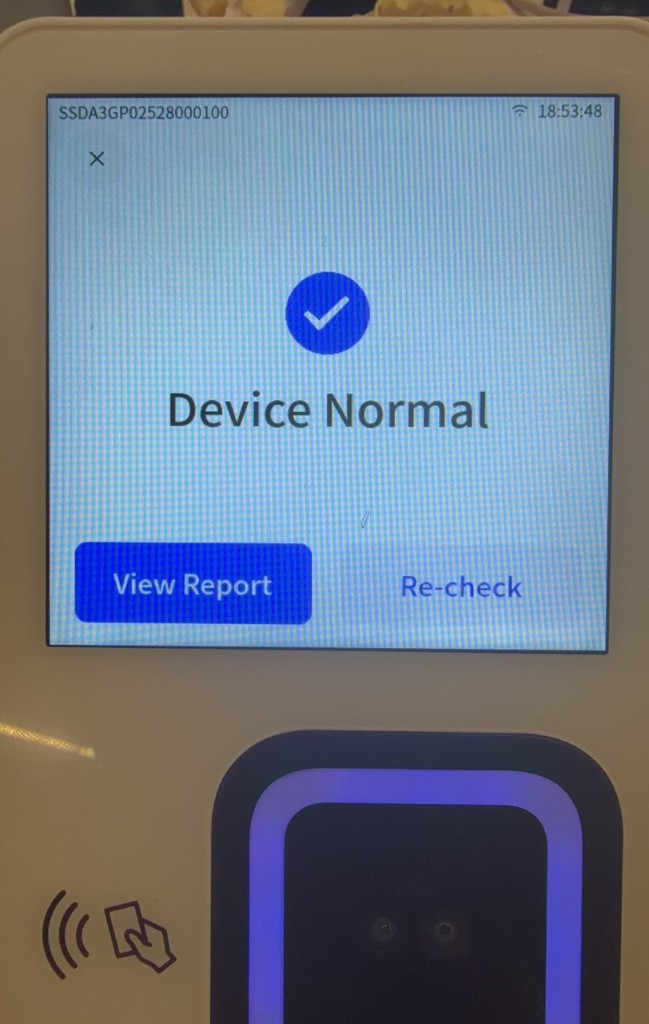
- If the check finishes without detecting an issue, confirm that the page displays
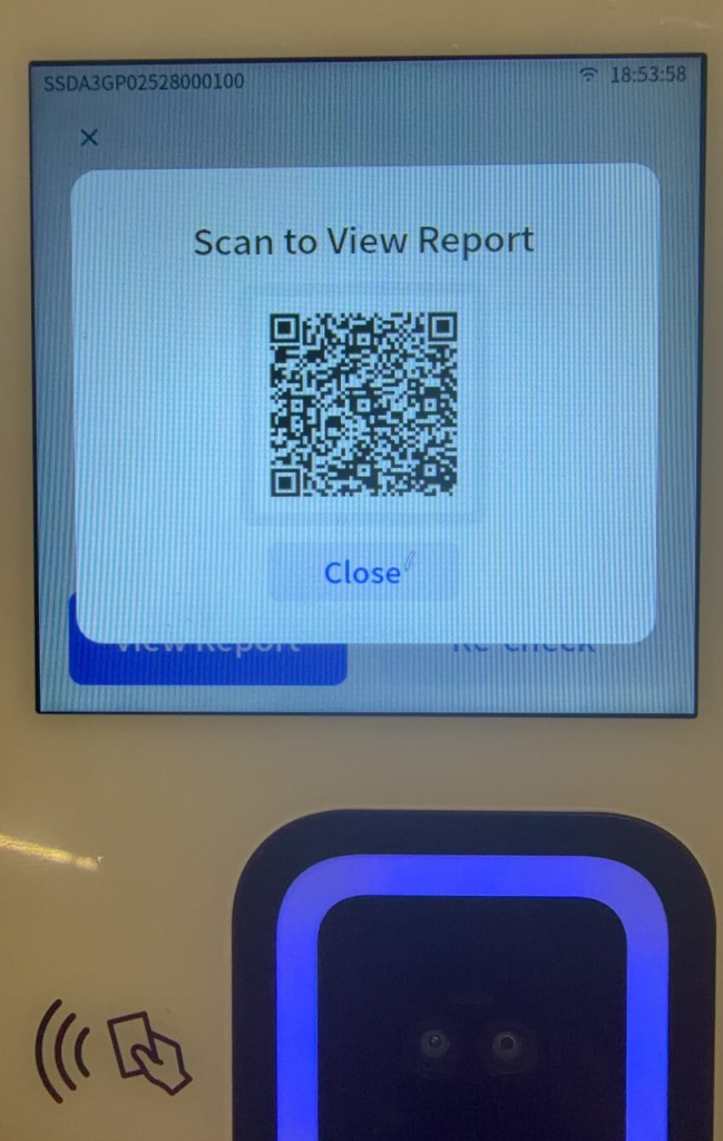
Device Normal. - Tap View Report to view the results. To run the check again, tap Re-check.
- To view the report on a phone, scan the QR code under Scan to View Report.
5.5.3 Viewing Device Operating Status
An administrator can search for a device by Device SN or device name under Device Management > Device List, then view its online status, component status, resource health information, and versions.
For complete descriptions of the device list and device dashboard, see "3.1.1 Device List" and "3.8.2 Device Dashboard" in the Admin Console User Manual.
5.5.4 Reporting a Device Issue
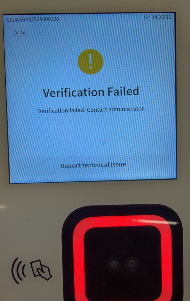
If registration or palm scan fails, or if a result or interface is abnormal, you can report the issue from the device.
- Tap Report technical issue on the verification failure page.
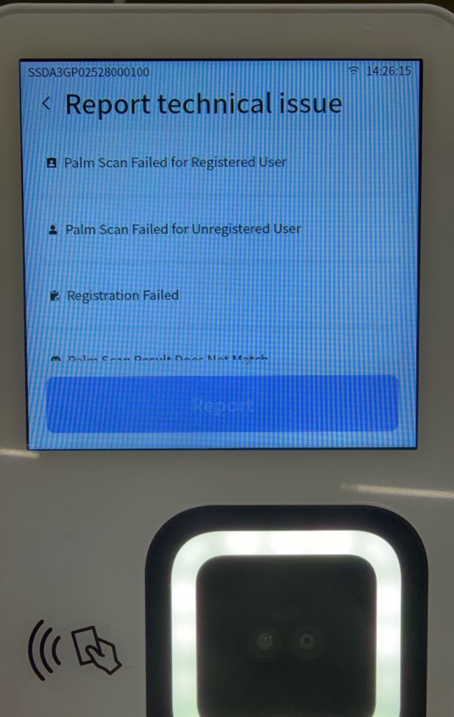
- Select the issue type that matches the on-site situation:
- Palm Scan Failed for Registered User
- Palm Scan Failed for Unregistered User
- Registration Failed
- Palm Scan Result Does Not Match
- Abnormal Interface Display
- Palm scan took too long
- Other Issues
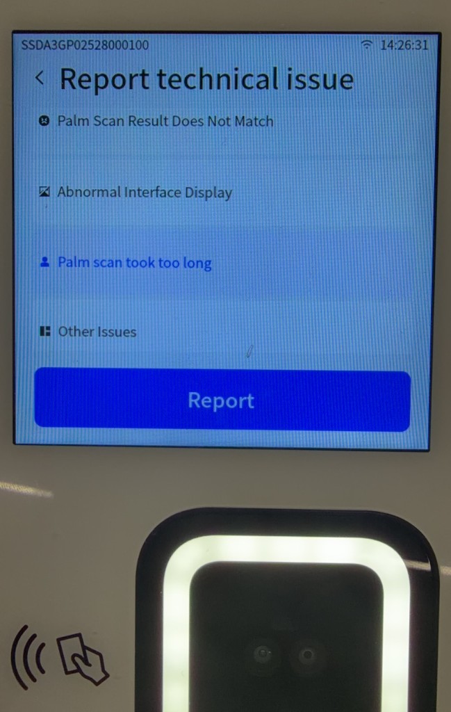
- Tap Report.
- When the device displays Collecting app logs, wait for log collection and reporting to finish.
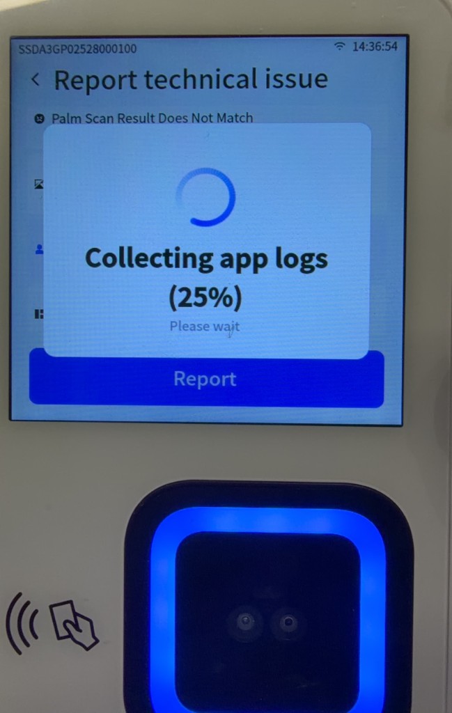
- When the page displays The issue has been reported, the issue has been reported successfully.
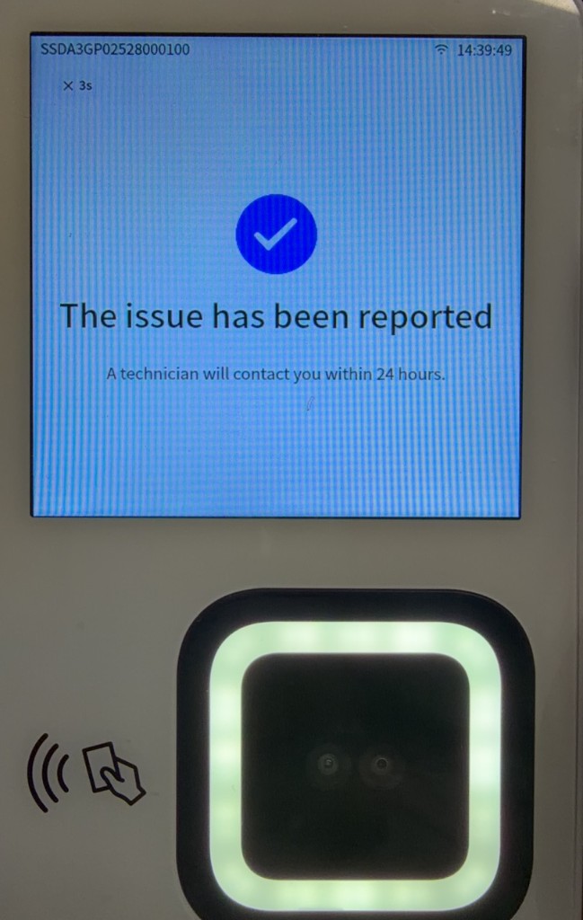
An administrator can view issue reports in the Admin Console. For details, see "3.7.1 Issue Reporting" in the Admin Console User Manual.
5.5.5 Viewing Device Logs
Device Logs require the cloud platform logging service to be enabled.
- Log in to the Admin Console and go to Device Management > Device Logs.
- Filter by Log ID, Log Date, Device, or Status.
- Locate the target log and click Download Logs.
For details, see "3.1.4 Device Logs" in the Admin Console User Manual.
5.5.6 Remote Device Maintenance
An administrator can issue remote commands to online devices from the Admin Console:
- Go to Device Management > Device Instruction.
- Select a command tab.
- Click Send Instruction.
- Select the target device and enter the required parameters.
- Click Submit.
- Return to the command list to view the execution status.
Common remote commands supported by the M3 include:
| Command tab | Function and considerations |
|---|---|
| Device Restart | Restarts the entire device remotely. |
| App Restart | Restarts the device application remotely; this does not restart the entire device. |
| Factory Reset | Restores the device to factory settings remotely. |
| Reset Palm Features | Resets palm print features on the device. |
| Reset Blacklist Data | Resets blocklist data on the device. |
| Clear Local Data | Clears local device data. |
| WiFi Settings | Distributes a WiFi name and password remotely. |
| Remote Door Open | Opens an access-controlled door remotely; supported only on the M3. |
For the complete remote command procedure, see "3.1.5 Remote Commands" in the Admin Console User Manual.
Warning
Remote clearing, reset, and door-opening operations pose security risks. Before issuing a command, confirm the target device, on-site conditions, and operator permissions.
5.5.7 OTA Upgrades and Version Maintenance
The M3 supports OTA tasks distributed from the Admin Console and manual installation of distributed upgrades on the device. The upgradable components are system firmware, module firmware, the application, and algorithm packages.
Before an upgrade, confirm that the device has a stable power supply and remains online. Do not disconnect power or trigger another upgrade during an upgrade or automatic restart.
5.5.7.1 Uploading an Upgrade Package
Before creating an Upgrade Campaign, upload the appropriate component Upgrade Package supplied by the manufacturer to the Admin Console:
- Log in to the Admin Console and go to Device Management > Upgrade Package.
- Click Add Upgrade Package.
- Select and upload the Upgrade Package, enter the version notes, and submit it.
- After the upload completes, confirm the version, device model, and other information in the Upgrade Package list.
Upgrade Packages are provided by the original manufacturer's Technical Support team. For instructions on adding, viewing details of, and deleting an Upgrade Package, see "3.1.6 Upgrade Package Management" in the Admin Console User Manual.
5.5.7.2 Creating an Upgrade Task
- Log in to the Admin Console and go to Device > Device OTA.
- Click Add Upgrade Campaign.
- Enter the campaign name, type, model, target version, task validity period, and release notes.
- Click Submit.
- In the campaign details, click Add Task.
- Select all devices or specific devices, then configure Silent Upgrade.
- Validate the devices and submit the task.
For the complete procedure, see "3.1.3 Device OTA" in the Admin Console User Manual.
5.5.7.3 Silent and Active Upgrades
| Upgrade method | Admin Console setting | Device behavior |
|---|---|---|
| Silent upgrade | Enable Silent Upgrade | The device downloads and installs the task automatically after receiving it. |
| Active upgrade | Disable Silent Upgrade | After receiving the task, on-site personnel tap Upgrade on the corresponding update page. |
For an active upgrade:
- Open the Setting page and scroll down.
- Tap the component entry that shows an update notification.
- View the target Version and Upgrade content:.
- Tap Upgrade.
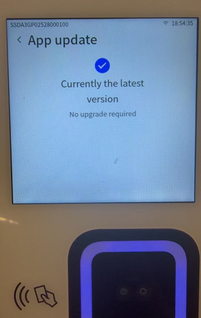
- Wait for the device to complete installation and restart automatically.
5.5.7.4 Upgrading the System, Module, Application, and Algorithm Package
Open the page for the component to be upgraded, view the current version, and follow the procedure in "5.5.7.3 Silent and Active Upgrades."
| Upgrade target | Device entry | Description |
|---|---|---|
| Main controller system firmware | Setting > System update | Wait for the device to restart automatically after installation. |
| Biometric module firmware | Setting > Module update | A module firmware Upgrade Package can include an algorithm package, depending on the package selected in the Admin Console. |
| Device application | Setting > App update | After installation and automatic restart, open App update again and confirm that the version was updated. |
| Algorithm package | Setting > Algo update | Algorithm packages can be upgraded independently. When creating an Upgrade Campaign, set Campaign Type to Algorithm. An algorithm can also be updated with a module firmware Upgrade Package. |
For multiple upgrades, use the following order:
Module update → System update → App update
Wait for each installation and restart to complete before proceeding to the next. Algorithm packages can be upgraded independently or included in a module firmware Upgrade Package.
5.5.7.5 Viewing Upgrade Results
After an upgrade, go to Setting and confirm the current version under Module update, System update, App update, or Algo update, as applicable. In the Admin Console, you can view task distribution progress, device upgrade status, and failure reasons.
5.6 Device Cleanup and Decommissioning
5.6.1 Clearing and Resetting the Device
5.6.1.1 Using Data Reset
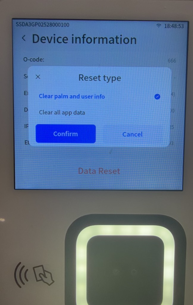
- Go to Setting > Device information.
- Tap Data Reset.
- Under Reset type, select:
- Clear palm and user info
- Clear all app data
- Tap Confirm.
Warning
Data Reset deletes data within the selected scope and cannot be undone. Before proceeding, confirm that service operations have stopped and that all necessary data checks are complete.
5.6.1.2 Using Factory Reset
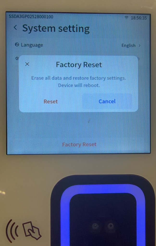
To restore the device to factory settings, go to Setting > System setting, tap Factory Reset, and confirm the operation.
Warning
Factory Reset clears device settings and service data. Afterward, you must reconfigure the network, authorization, IoT activation, and service settings. Use this feature only when decommissioning the device or under guidance from After-Sales Support.
The Admin Console also provides remote commands such as Reset Palm Features, Clear Local Data, and Factory Reset. For the distribution procedure, see "5.5.6 Remote Device Maintenance."
5.6.2 Deleting a Device from the Admin Console
Before deleting a device, disassociate it from its scene. The Admin Console prevents deletion while the device is still associated with a scene.
- Edit the original scene under Verification > Scene Management.
- Remove the target device from Associated device and save the scene.
- Go to Device Management > Device List.
- Locate the target device by Device SN or device name.
- Click Delete and confirm.
For the complete device deletion procedure, see "3.1.1.4 Delete Device" in the Admin Console User Manual.
After a device is deleted, its Palm Feature Database and rules are removed, and the device can no longer perform palm scans. Existing historical Verification Records are unaffected.
Warning
Before deleting a device, confirm that it no longer supports an active service and notify affected users in advance.
5.7 FAQ
5.7.1 The Device Has No Display After Power-On
- Confirm that you are using the 12 V power adapter supplied with the device.
- Check that the power outlet, power adapter, and device power cable are securely connected.
- Confirm that the adapter output meets the device requirements.
- Reconnect the power. If the display remains blank, contact After-Sales Support.
5.7.2 The Device Reports That It Is Not Registered or Not Activated
- Confirm the Device SN on the device label or under Device information.
- Ask an administrator to confirm that this Device SN has been entered in the Admin Console.
- After confirming that the device is online, scan a valid IoT activation QR code again.
- If the device has been activated but still reports that it is not registered after a restart, tap the retry button on the page.
- If the page does not respond, press the concealed reset button on the left side with a paper clip to restart the device.
- If the issue persists, contact After-Sales Support.
5.7.3 A Registered User Is Told That No Physical Card Number Was Read
The M3 access control service requires a Physical Card Number for each user. Ask an administrator to open the user edit page, enter an actual card number or a virtual card number assigned by the service in Physical card number, save the change, and perform another palm scan.
5.7.4 No Wiegand Output or the Door Does Not Open
- Confirm that the user's palm scan verification succeeded and the user has access permission for the current scene.
- Confirm that the user has a Physical Card Number.
- Check the 12 V, GND, D0, and D1 wire sequence. Confirm that D0 and D1 are not reversed and that the device and controller share a common ground.
- Go to Setting > Output and confirm that the correct Wiegand format is selected under Access Mode.
- Confirm that the device and controller use the same Wiegand bit length.
- Under Card Uid Rule, confirm that the byte order matches the controller.
- Check for loose or poorly connected terminals.
5.7.5 Wiegand Output Is Unstable
- When using RVV 0.5 cable, keep the transmission distance within 100 m.
- When transmitting over a single conductor in a CAT5e cable, keep the distance within 50 m.
- For a long Ethernet cable carrying GND, D0, and D1, reinforce the ground connection.
- Keep signal cables away from high-voltage power and interference sources, and confirm that the device and controller share a common ground.
5.7.6 The Access Controller Parses an Incorrect Card Number
- Convert the Physical Card Number entered in the Admin Console to binary and confirm that it does not exceed the data-bit capacity of the selected Wiegand format.
- Select the correct format according to "5.4.10.4 Checking the Wiegand Bit Length."
- Under Card Uid Rule > Select Endian, switch between Big Endian and Little Endian to match the controller's parsing rule.
- Perform another palm scan and verify the card number received by the controller.
5.7.7 RS485 Communication Is Abnormal
- Check whether the positive and negative RS485 terminals are reversed, and ensure that all devices share a common ground.
- Use 0.5–0.75 mm² shielded twisted-pair cable.
- Use a daisy-chain bus topology, avoid star branches, and keep the bus away from high-voltage lines.
- Keep the bus within 1,200 m. A repeater is recommended when the length exceeds 500 m.
- Connect a 120 Ω termination resistor at the end of the bus as required by the controller.
5.7.8 The Relay Opens the Door in the Opposite Direction
- Determine whether the lock is fail-safe or fail-secure.
- Check the NO, NC, and COM wiring on the access control power supply.
- Test the lock with power disconnected and confirm that its behavior meets on-site fire safety and security requirements.
- If the correct wiring remains unclear, disconnect power and contact qualified access control personnel.
5.7.9 Does the Device Support PoE Power?
The M3 does not support PoE power. Use the supplied 12 V power adapter.
5.7.10 Ethernet Does Not Work
- Go to Setting > Network setting > WiFi and turn off the wireless network.
- Check the Ethernet cable, RJ45 connectors, router, and switch ports.
- Confirm that both ends of the Ethernet cable use the same standard wire sequence.
- Under Ethernet, confirm that the network is enabled and check the DHCP or Static configuration.
Enabling Ethernet and WiFi on the M3 at the same time causes a conflict. WiFi must be turned off when using a wired network.
5.7.11 Cannot Find or Connect to WiFi
- Move closer to the wireless router and eliminate metal obstructions and weak-signal conditions.
- Some production batches support only 2.4 GHz. Confirm that the router has 2.4 GHz enabled.
- A dual-band device may have compatibility issues with an unsecured 5 GHz network. Set a password or use 2.4 GHz.
- Use a WiFi password containing letters and numbers, and avoid special characters.
- When connecting to an iPhone hotspot, you can enable "Maximize Compatibility" and change the phone name to contain only English letters or digits.
- If WiFi is connected but cannot access the network, confirm that Ethernet is disabled and that the router has Internet access.
5.7.12 The Device Application Freezes or the Screen Goes Black
- Wait for the device application to recover automatically.
- If it does not recover, press the concealed reset button on the left side to restart the device.
- Go to Setting > App update and check for available updates.
- If the issue recurs, report the device issue and contact After-Sales Support.
5.7.13 OTA Upgrade Is Abnormal
- Confirm that the device has a stable power supply and remains online. Prefer a wired network.
- Check whether the Upgrade Task has expired or another task of the same type is in progress.
- Wait for the current task to finish before trying again. Do not trigger multiple upgrades simultaneously.
- For multiple component upgrades, use the order Module update → System update → App update, waiting for each restart to finish before continuing.
- If a download times out, restore a stable network and try again.
- Do not disconnect power during installation. If the device cannot start normally or repeatedly fails, contact After-Sales Support.
5.7.14 Authorization Fails or Has Expired
- Distinguish License authorization from IoT activation. An abnormal authorization page relates to the License; a report that the device is not registered or that the activation code is invalid relates to IoT activation.
- For online authorization, check the network and device time.
- Confirm that the authorization QR code corresponds to the current device and APP ID and remains valid.
- If authorization has expired, contact Sales or Technical Support for a new authorization QR code.
- Repeated authorization may consume the available Number of Licenses. Confirm the license quantity before proceeding.
5.7.15 Palm Scan Is Slow or Recognition Fails
- Remove the protective film from the camera and clean the camera area.
- Keep the palm center clean and free of visible dirt or perspiration.
- Hold the palm 5–12 cm from the device with its center facing the camera.
- Avoid strong backlight, obstructions, rapid movement, and excessive tilt.
- Check the device's network quality.
- After repeated failures, ask an administrator to check the user's registration status, scene permissions, and palm print data.
5.7.16 Palm Scan Succeeds but No Verification Record Is Found
- Confirm that the device is online and has completed IoT activation.
- Confirm that the device is associated with the correct scene.
- Confirm that the user has completed Palm Registration and activation.
- Confirm that the verification rule and Additional Verification settings have taken effect.
- Under Verification Records, check the time, scene, and user filters.
5.7.17 H5 Registration or Device Scan QR Registration Fails
- Ask an administrator to confirm that the user has been created in the Admin Console and that the User ID, Username, mobile number, and other information match the H5 entries.
- A registration QR code is valid for 15 minutes. Generate a new one after it expires.
- Confirm that the device is online.
- Clean the device camera and increase the clarity of the phone display.
- Confirm that the device is in Registration - Device Scan QR mode.
5.7.18 Phone Scan QR Registration Fails
- Confirm that the device is in Registration - Phone Scan QR mode.
- Confirm that the corresponding registration method is enabled for the tenant.
- In a closed scene, confirm that the user has been created in the Admin Console and that the information entered on the phone matches the Admin Console records.
- Capture the palm again and scan the new QR code generated by the device.
5.7.19 Additional Verification by Device QR Code Scan Fails
- Confirm that Device QR Code Scan has been selected for the tenant's Additional Verification.
- Check whether the authentication QR code has expired. Generate a new one if necessary.
- If the device has waited more than 60 seconds for a scan, perform another palm scan to trigger Additional Verification again.
- Clean the camera and increase the clarity of the phone display.
- Confirm that the user meets the registration and Additional Verification conditions for the current project.
5.7.20 The Device Still Reports an Unregistered Palm After Mobile Palm Registration
Mobile Palm Registration consists of mobile preregistration and device activation. After confirming that mobile preregistration succeeded, switch the device to Recognition and perform the first palm scan with the preregistered palm to activate it. Normal verification becomes available only after this initial activation.
5.7.21 The Device Settings Password Has Been Forgotten
The initial device password is 000000. If the password was changed and then forgotten, contact After-Sales Support to reset it. To prevent unauthorized settings changes, do not post the password near the device.
5.7.22 Device Health Check Reports Insufficient Disk Space
An insufficient disk space warning may affect OTA package download and installation.
- Pause new OTA Upgrade Tasks.
- Confirm whether routine palm scan functions operate normally.
- Report the device issue and contact After-Sales Support to clear storage space.
- After After-Sales Support confirms that space is available, distribute the Upgrade Task again.
5.7.23 There Is No Voice Prompt or the Volume Is Too Low
- Go to Setting > System setting and increase the volume.
- Check whether the speaker opening on the rear housing is obstructed by a bracket, decorative panel, or foreign object.
- Restart the device and test again.
- If there is still no sound, contact After-Sales Support.
5.7.24 What Is the Difference Between Registration and Recognition Modes?
- Registration modes capture a palm and bind it to user information. They are not used for routine access verification.
- Recognition is used for routine verification of registered users and for the first offline activation of Mobile Palm Registration users.
After completing batch user registration, switch the device back to Recognition.
5.7.25 A Palm Is Registered Twice or the Palm Database Is Full
If the device reports that a palm is already registered or is a duplicate, ask an administrator to determine whether the palm is already bound to another user. To register it again, delete the existing palm print record before capturing it again.
If the network and user information are normal but registration still fails, ask an administrator to check the tenant's Palm Database capacity. If it is full, delete unused palm prints or request a capacity increase.
5.7.26 The Device Reports User Not Found for a Registered User
- Confirm that the device's current tenant is the same tenant under which the user was registered.
- Confirm that the current scene's verification rule includes the user.
- If the user was just registered on another device, wait for feature synchronization and try again.
- If the issue persists, ask an administrator to check the User Status and contact After-Sales Support to resolve abnormal local feature synchronization.
5.7.27 Recognition Triggers High Similarity or Additional Verification
When the system cannot uniquely determine the user's identity, it may report High Similarity or require Additional Verification.
- Follow the device prompts to enter the last four digits of the mobile number or a custom numeric field, or complete Additional Verification by device QR code scan.
- If Additional Verification fails, confirm that the corresponding mobile number or custom field is present for the user in the Admin Console.
- If High Similarity is triggered frequently, capture higher-quality palm information and check for duplicate users or palm prints.
5.7.28 The Device Reports Restricted Access
After multiple Palm Liveness Detection failures within a short period, the system may temporarily restrict further recognition attempts.
- Wait for a period and try again.
- Adjust the palm scan distance and angle, keeping the palm center facing the camera.
- Avoid strong backlight and clean the camera.
- If normal operation continues to be restricted, ask an administrator to check the Blocklist status.
5.7.29 OTA Upgrades Cannot Be Performed on an Internal Network
The device must access the OTA service configured for the project to download Upgrade Packages. If the internal network restricts external access, ask an administrator to confirm the network policy, service address, and access permissions. If necessary, move the device to a network that can access the OTA service before upgrading.
5.7.30 The Remote Door Open Command Fails
- Confirm that the target device is an M3 and is currently online.
- Confirm that the administrator has remote door-opening permission and selected the correct device.
- Check the relay, Wiegand, access controller, and door lock wiring.
- View the execution status in the command list. If it failed, issue the command once more.
- If the command reports success but the door does not open, ask qualified access control personnel to inspect the controller and door lock circuit.
5.7.31 Installation Location and Waterproofing Requirements
The M3 is not waterproof. Install it indoors or in a sheltered semi-outdoor area away from rain, humidity, and strong backlight. For wall installation, a height of 1.4–1.6 m is recommended. Adjust it based on the average height of on-site users and the turnstile structure.
5.7.32 Which Network Connection Is Recommended?
Use a wired network whenever possible. A wired network is generally more stable than WiFi. WiFi is not recommended as the standard connection for an on-site deployment of more than 10 devices.
5.7.33 What Are the Wired Network Cabling Requirements?
- A single Ethernet cable segment must not exceed 100 m; keeping it within 80 m is recommended.
- Do not place connectors in the middle of an Ethernet cable, and avoid sharp bends, compression, and high-voltage interference.
- Use CAT5e or higher-grade cable and standard RJ45 connectors. Before installation, use a cable tester to confirm that the line works correctly.
- Protect cables with PVC conduit or wiring ducts.
- Provide a stable power supply for each device and avoid sharing a power circuit with high-power equipment.
5.7.34 How Much Network Bandwidth Is Required for Different Numbers of Devices?
The following values are recommended. Adjust the actual bandwidth based on on-site network quality and service concurrency:
| Number of devices | Recommended bandwidth and network topology |
|---|---|
| 1–4 | Shared bandwidth of at least 20 Mbps; devices can connect directly to a router. |
| 5–30 | Bandwidth of at least 100 Mbps with an enterprise-grade router and managed switches. |
| 31 or more | A dedicated line of at least 100 Mbps with an enterprise-grade router, Gigabit switches, and VLANs configured according to the project network plan. |
5.7.35 What Are the Restrictions on Switch Deployment?
Do not cascade more than three switches on the same LAN. Too many network layers can increase latency and reduce stability.
5.7.36 What Lighting Conditions Does the Device Require?
Do not use the device outdoors with strong backlight or where brightness changes dramatically. Adjust the device angle so that light falls evenly on the palm and strong light does not shine directly into the camera.
5.7.37 How Should a Palm Scan Be Performed?
- Extend the palm naturally with its center facing the center of the camera.
- Keep the palm approximately 5–12 cm from the device.
- Minimize palm tilt and rotation, and keep the palm steady during recognition.
5.7.38 What Are the Resolution and Frame Rate of the RGB and Infrared Cameras?
Both the RGB camera and infrared camera have a resolution of 1600 × 1200 and a frame rate of 30 FPS.
5.7.39 What Camera Specifications Does Mobile Palm Registration Require?
A mobile device camera with at least 3 megapixels is sufficient.
5.1 Device Overview and Installation
This section describes the main components of the M3, its installation environment, wall and turnstile installation methods, access control wiring, startup procedure, and palm scan precautions.
5.1.1 Device Exterior and Interfaces
The main components of the M3 include the NFC card reader area, display, palm scan camera module, concealed reset button on the left side, pigtail interfaces, and speaker.
| Component | Description |
|---|---|
| NFC card reader area | Reads access cards. Card-reading capability depends on the on-site access control configuration. |
| Display | Shows device pages, operation prompts, and processing results. |
| Palm scan camera module | Captures and recognizes palm information. |
| Concealed reset button on the left side | Press it with a paper clip or similar pointed tool to perform a hardware restart if the device malfunctions. |
| Speaker | Plays voice prompts and notification sounds. |
| Pigtail interfaces | Include USB HOST, relay, Wiegand, and RS485 interfaces. |
The pigtail interfaces serve the following purposes:
| Interface | Purpose |
|---|---|
| USB HOST | Connects supported USB peripherals. |
| Relay | Outputs a dry-contact signal for connection to a dedicated access control power supply or door lock control circuit. |
| Wiegand | Outputs Wiegand signals to the access controller. |
| RS485 | Communicates with the access controller over an RS485 bus. |
Note
The M3 does not support PoE power. Use the supplied 12 V power adapter.
5.1.2 Indicator Lights
| Light status | Device status |
|---|---|
| Dim blue | Sleep mode |
| Dim white | Standby |
| Bright white fill light | Registering or recognizing a palm |
| Flashing orange | The palm is too close to the device |
| Green on | Recognition succeeded |
| Red on | Recognition failed |
5.1.3 Installation and Operating Environment
The M3 is intended for indoor or sheltered semi-outdoor environments. Observe the following requirements during installation and use:
- The device is not waterproof. Prevent liquids and dust from entering it.
- Do not use the device in extremely cold, hot, or humid environments or near heat sources.
- Do not drop, strike, throw, or bend the device.
- Use the device in a clean, low-dust environment, and leave sufficient clearance around it for heat dissipation.
- Keep accessories and disassembly tools out of the reach of children.
- Do not install the device near a window or outdoors where there is strong backlight. If necessary, adjust the device angle so that light falls evenly on the user's palm.
- Adjust the installation height to the average height of on-site users. For details, see "5.1.4.1 Wall Installation."
5.1.4 Installing the Device
5.1.4.1 Wall Installation
An 86-type junction box is recommended for wall installation. Depending on site conditions, set the installation height between 1.4 and 1.6 m.
- Route the access control wiring harness through the round hole in the bracket.
- Secure the bracket to the 86-type junction box using the M4 screws supplied with the device.
- Connect the access control harness to the device pigtail, then arrange the harness inside the junction box without pinching or pulling it.
- Align the slots on the device with the tabs on the bracket, then snap the device onto the bracket.
- Tighten the two M2.5 screws on the side of the device to secure it to the bracket.
Note
Disconnect all relevant power supplies before installation. Restore power only after confirming that the wire sequence, insulation, and fastening are correct.
5.1.4.2 Turnstile Installation
The M3 can output a door-open signal to an access controller through Wiegand or a relay. It can also connect through RS485 as required by the project integration. The access controller parses the signal and opens the turnstile. Follow the turnstile manufacturer's requirements for the mounting structure, cutout dimensions, and fastening method.
- Determine the device position and camera height based on the turnstile structure.
- Secure the device at the turnstile mounting position.
- Connect the device pigtail to the access controller according to the selected output method.
- Check the power supply, grounding, and signal wire sequence.
- After configuring permissions and device output in the Admin Console, test opening the turnstile with a palm scan.
5.1.5 Connecting Access Control Wiring
Before wiring, determine whether the site will use Wiegand, RS485, or a relay to open the door. Installation must be performed by qualified access control personnel.
5.1.5.1 Connecting Wiegand or RS485
For Wiegand, connect the device's 12 V, GND, D0, and D1 wires according to the access controller interface definitions. Do not reverse D0 and D1. The device and controller must share a common ground.
For RS485, connect the positive and negative signal terminals of the device to the corresponding controller terminals, and ensure that all devices on the bus share a common ground.
Note
The Wiegand output format and byte order must match the access controller. For long cable runs, use suitable cables and keep them away from high-voltage power lines.
5.1.5.2 Connecting Relay Dry Contacts
The relay outputs a dry-contact signal and can connect to the control terminal of a dedicated access control power supply. Select NO or NC according to the door lock type.
5.1.5.3 Connecting an NO or NC Door Lock
Door locks can be fail-safe (open when power is removed) or fail-secure (remain closed when power is removed). Select the lock type based on fire safety, security, and on-site business requirements, and wire it according to the NO, NC, and COM terminal definitions of the dedicated access control power supply.
The following example connects SS and NO for a fail-safe lock:
- P1: When power to the lock is removed, the lock physically releases and the door opens.
- P2: When the lock is powered but the M3 is not, the relay is open and the NO terminal is disconnected. The powered lock remains locked and the door stays closed.
- P3: When both the lock and M3 are powered, successful verification energizes the relay and cuts power to the lock, opening the door. If verification fails, the relay remains in its default state and the door stays locked.
Warning
Incorrect NO, NC, or power-circuit wiring may cause the lock to operate opposite to the intended behavior. Before powering the lock, use a multimeter to confirm the terminal states and verify the door-opening strategy during a power outage.
5.1.5.4 Receiving a GPIO Signal and Outputting a Relay Signal
The M3 can receive an external GPIO signal and output a control signal through the relay. Wire the external device according to its voltage level, common-ground, and trigger requirements.
5.1.6 Powering On the Device
- Confirm that the device is securely installed and all cables are connected according to the interface definitions.
- Connect the supplied 12 V power adapter to the device power cable.
- Turn on the power and wait for the device to start and display the operation page.
To restart the device, open the Setting page and tap Device Restart, or press the concealed reset button on the left side with a paper clip or similar pointed tool.
5.1.7 Palm Registration and Recognition Precautions
Before registering or recognizing a palm, remove the protective film from the camera area and keep both the camera and palm clean.
- Extend the palm naturally with its center facing the center of the palm scan camera module.
- Keep the palm approximately 5–12 cm from the device.
- Hold the palm steady until capture or recognition is complete.
- Face the palm toward the device with a tilt angle of less than 30°.
- Keep the palm rotation angle below 180°.
- Do not obstruct the palm or use the device in strong backlight.
5.2 Initial Connection and Activation
5.2.1 Initial Connection Process
When connecting the M3 to the Palm Application Platform for the first time, complete activation in the following order:
- Configure Ethernet or WiFi and ensure that the device can connect to the network.
- Complete License authorization and confirm that the device is licensed to use palm scan algorithms.
- Enter the device name and Device SN in the Admin Console.
- Use the device to scan the activation QR code generated by the Admin Console to complete IoT activation and bind the device to the Admin Console environment.
- Associate the device with the appropriate scene in the Admin Console, then configure on-device Scene Strategy A or B, Verification Rules, and user permissions.
Description
License authorization and IoT activation are separate processes. License authorization grants access to palm scan algorithms, while IoT activation connects the device to the current Admin Console environment. Complete both processes independently.
5.2.2 Configuring the Device Network
The device must be online to perform online authorization, IoT activation, configuration synchronization, verification record reporting, and OTA upgrades.
- Tap the settings button in the upper-left corner of the device home page.
- Enter the device settings password in the Please input password window. The initial password is
000000. - Tap Confirm to open the Setting page.
- Tap Network setting.
- Select WiFi or Ethernet based on the on-site network.
Tip
Use a wired network whenever site conditions permit. WiFi is not recommended for deployments with more than 10 devices.
Observe the following requirements when planning a wired network:
- A single Ethernet cable segment must not exceed 100 m; keeping it within 80 m is recommended. Do not place connectors in the middle of the cable, bend it sharply, or compress it.
- Use CAT5e or higher-grade cable and standard RJ45 connectors. Before installation, use a cable tester to check the wire sequence and connectivity.
- Protect cables with PVC conduit or wiring ducts. Use a separate power outlet for each device and avoid sharing a circuit breaker with other equipment.
- Do not cascade more than three switches on the same LAN.
| Number of devices | Recommended bandwidth and network topology |
|---|---|
| 1–4 | Shared bandwidth of at least 20 Mbps; devices can connect directly to a router. |
| 5–30 | Bandwidth of at least 100 Mbps with an enterprise-grade router and managed switches; use no more than four managed switches in one network. |
| 31 or more | A dedicated line of at least 100 Mbps, an enterprise-grade router, and Gigabit switches are recommended. Configure VLANs according to the project network plan. |
5.2.2.1 Connecting to a Wired Network
- Use an Ethernet cable to connect the network interface on the device pigtail to a router or switch.
- Go to Setting > Network setting > WiFi.
- Turn off the wireless network switch.
- Return to Network setting and tap Ethernet.
- Enable Ethernet.
Note
Enabling Ethernet and WiFi on the M3 at the same time causes a network conflict that prevents the wired network from operating correctly. Always turn off WiFi before using a wired network.
5.2.2.2 Selecting the Ethernet IP Mode
Ethernet supports two IP modes, DHCP and Static. The default is DHCP.
- Go to Setting > Network setting > Ethernet.
- Enable Ethernet.
- Tap IP Mode.
- Under Select IP Mode, select DHCP or Static.
After you select DHCP, the device automatically obtains an IP address from the network.
After you select Static, enter the IP address, gateway, DNS, and other information according to the on-site network plan, then tap Apply.
5.2.2.3 Connecting to WiFi
- Go to Setting > Network setting > WiFi.
- Turn on the wireless network switch.
- Select the target WiFi network from the list.
- If the network requires a password, enter it and connect.
- Wait for the device to connect.
Note
Wireless capabilities vary between M3 production batches. Some batches support only 2.4 GHz, while others support both 2.4 GHz and 5 GHz. If the device cannot find a 5 GHz network, use a 2.4 GHz network. Unsecured 5 GHz networks may have compatibility issues; use password-protected WiFi or switch to 2.4 GHz. A WiFi password containing a combination of letters and numbers is recommended.
To configure a static IP for the current WiFi network, tap the information button next to the connected network, select static IP mode on the network details page, and enter the IP address, subnet mask, gateway, and DNS according to the on-site network plan.
5.2.2.4 Managing Saved WiFi Networks
- Go to Setting > Network setting > WiFi.
- Tap Saved in the upper-right corner.
- View saved WiFi networks on the Saved networks page.
To delete a saved WiFi network, tap the delete button to its right.
To add a WiFi network manually:
- On the Saved networks page, tap Add Wifi.
- Enter the WiFi name in ssid.
- Enter the WiFi password in password.
- Tap Confirm. To cancel, tap Cancel.
5.2.2.5 Connecting to a Hidden WiFi Network
- Go to Setting > Network setting > WiFi.
- Turn on the wireless network switch.
- Tap Other... in the WiFi list.
- On the Join hidden network page, tap Network and enter the hidden WiFi network's SSID.
- Tap Security and select the security type configured on the router.
- If the network requires a password, enter it in Password.
- Tap Join and wait for the device to connect.
Note
The SSID of a hidden WiFi network is case-sensitive. Enter it exactly as configured on the router.
5.2.2.6 Resetting Network Settings
Network Reset restores the device network settings to their defaults.
- Go to Setting > Network setting.
- Tap Network Reset.
- Tap Reset in the confirmation window.
- Reconfigure WiFi or Ethernet after the reset.
5.2.3 Completing Device Authorization
5.2.3.1 Authorization Preparation
Complete the following preparations before authorization:
- Confirm whether the device was permanently authorized at the factory. A permanently authorized device does not require on-site authorization.
- If the device has not been authorized or its authorization has expired, contact Sales or Technical Support for an authorization QR code.
- Online authorization is recommended by default. Confirm that the device can access the authorization service.
- Use offline authorization only as a fallback in exceptional cases.
- Print the authorization QR code on paper so that the device camera can scan it more easily.
When requesting an authorization QR code, provide the APP ID and specify the number of devices, authorization term, and whether online or offline authorization is required.
5.2.3.2 Online and Offline Authorization
| Authorization method | Network requirement during authorization | Use case |
|---|---|---|
| Online authorization | The device must be able to access the authorization service over the network. | Recommended by default for network-connected deployments. |
| Offline authorization | Authorization information is embedded in the QR code, so injecting it by scanning does not require a network. | A fallback for exceptional cases involving a completely offline standalone device. |
Description
An offline authorization QR code already contains the authorization information, so scanning and injecting it does not require a network. IoT activation, configuration synchronization, and online services still require network access.
For online authorization, identify the device's access path based on the deployment network:
- If the device can access the Internet, it can access the authorization service directly or complete authorization and authentication through the Backend Service Gateway.
- If the device is on a LAN with Internet access, it can reach the authorization service through the Backend Service Gateway on the same network.
- If neither the device nor the Backend Service Gateway can access the Internet, confirm that a working local authorization service has been deployed for the project. Otherwise, use offline authorization.
5.2.3.3 Scanning the Authorization QR Code
- On the Device authorization page, confirm that the current status is
Unauthorized, then tap Scan the QR code. - Hold the authorization QR code approximately 10 cm from the palm scan camera module.
- Wait for the device to scan the code.
- After the scan succeeds, wait for the module to restart automatically.
After the module restarts, the device displays the authorization result and validity period. If authorization fails, return to the authorization page and scan again. If it fails repeatedly, check the QR code, device time, and network, then contact After-Sales Support.
5.2.3.4 Viewing Authorization Status
After authorization succeeds, the device displays Authorization successful. You can subsequently go to Setting > Authorization, confirm that the status is Authorization Active, and view Authorization status, Validity period, APP ID, and Authorization path. When authorization expires, obtain a new authorization QR code and authorize the device again.
5.2.4 Registering a Device in the Admin Console
- Log in to the Admin Console and go to Device Management > Device List.
- Click Add Device.
- Enter a device name and the Device SN shown on the device label.
- Verify the information, then click Submit.
- Return to the device list and confirm that the device name and Device SN are correct.
The Device SN uniquely identifies the device and cannot be changed after entry. For batch device registration, see "3.1.1.1 Device Registration" in the Admin Console User Manual.
5.2.5 Activating the Device and Binding the Admin Console Environment
After registering the device, complete IoT activation to connect it to the current Admin Console environment.
- Confirm that the device has completed License authorization, is connected to the network, and has been registered in the current Admin Console.
- On the Device List page in the Admin Console, click Device Activation to generate an activation QR code.
- Scan the activation QR code with the M3.
- After activation succeeds, return to the device list and confirm that the device status has changed from not activated to online or offline.
For the complete activation QR code procedure, see "3.1.1.2 Device Activation and Environment Binding" in the Admin Console User Manual.
Note
Activation QR codes expire. If a code has expired, generate a new one in the Admin Console.
If activation fails, follow the applicable instruction:
This device is not registered: Confirm that the Device SN has been entered in the Admin Console.The QR code is not a valid activation code: Confirm that you scanned a device activation QR code.This activation code has expired: Generate a new activation QR code.- Network error or prolonged lack of response: Check the device network and try again.
5.2.6 Associating the Device with a Scene
After activation, associate the device with the scene where it will be used.
- Log in to the Admin Console and go to Verification > Scene Management.
- Select the target scene group.
- Locate the target scene and click Edit. If it does not exist, click Add Scene.
- Select the M3 under Associated device.
- Select on-device recognition strategy A or B under Scene Strategy.
- To restrict users and access times, enable Verification Rule and select a verification rule.
- Click Submit.
A device cannot be associated with multiple scenes at the same time. To change its scene, first remove it from Associated device in the original scene, then add it to the new scene.
For instructions on creating and editing scenes, see "3.2.2 Scene Management" in the Admin Console User Manual. For rules covering authorized users, valid dates, blocked dates, and time periods, see "3.4 Verification Rules."
5.3 Basic Device Settings
This section describes language, volume, time, password, device information, and restart settings.
5.3.1 Opening the Setting Page
- Tap the settings button in the upper-left corner of the device home page.
- Enter the device settings password in the Please input password window. The initial password is
000000. - Tap Confirm to open the Setting page. To cancel, tap Cancel.
5.3.2 Setting the Device Language
- Go to Setting > System setting.
- Tap Language.
- Select the desired language.
A selection indicator appears next to the current language.
5.3.3 Setting the Device Volume
- Go to Setting > System setting.
- Locate the volume slider.
- Drag the slider left or right to adjust the volume of voice prompts and notification sounds.
5.3.4 Viewing and Synchronizing Device Time
- Go to Setting > Time Configuration.
- View Time Zone and Current Time.
- To synchronize the time again, tap Resync Time.
- After synchronization succeeds, confirm that the device time is correct.
You can only view and resynchronize the time on the device; you cannot change the time zone directly. After the device is activated for the current tenant, its time zone is synchronized with the time zone configured in the Admin Console. A super administrator manages that setting under System > System Settings > Timezone Settings.
5.3.5 Changing the Device Settings Password
- Go to Setting.
- Tap Password.
- Enter a new password.
- Tap Confirm.
Note
Store the new password securely. If you forget it, contact After-Sales Support to reset it.
5.3.6 Viewing Device Information
Go to Setting > Device information to view the current tenant, scene, service endpoint, Device SN, IP address, Ethernet MAC, WLAN MAC, and other information.
To view component versions, return to the Setting page and scroll down:
| Entry | Information displayed |
|---|---|
| System update | System version |
| App update | Application version |
| Module update | Module version |
| Algo update | Algorithm version |
5.3.7 Restarting the Device
The M3 supports scheduled automatic restarts, restarts from the Setting page, and restarts using the concealed reset button.
Configure automatic restart
- Go to Setting > Soft reboot.
- Enable Soft reboot mode.
- Select a start time under Select start time.
- Tap Confirm.
Each day, the device automatically restarts within the configured time range when no one is performing a palm scan. Enable this feature for devices that run continuously for long periods.
The device selects an idle period within one hour after the chosen start time to restart, minimizing disruption to on-site operations.
To disable automatic restart, turn off Soft reboot mode, then tap Confirm.
Restart from the Setting page
- Open the Setting page and scroll to the bottom.
- Tap Device Restart.
- Tap Restart in the confirmation window and wait for the device to restart.
5.4 Service Activation and Palm Scan
5.4.1 Switching Device Registration and Recognition Modes
The M3 supports four registration methods: phone scan QR, device input, device scan QR, and Mobile Palm Registration. Select mode on the device currently provides only the following four options:
- Recognition
- Registration - Phone Scan QR
- Registration - Device Input
- Registration - Device Scan QR
Mobile Palm Registration is not a separate device registration mode. The user first preregisters a palm through a mobile App or the Mobile Palm Registration H5 page, then activates it with the first palm scan in Recognition mode.
| Registration method | Description | Device mode |
|---|---|---|
| Phone Scan QR Registration | The device captures the palm first. The user scans the QR code displayed by the device with a phone and enters user information. | Registration - Phone Scan QR |
| Device Input Registration | The device captures the palm first, after which the user information is entered on the device. | Registration - Device Input |
| Device Scan QR Registration | The user first generates a QR code on the H5 registration page. After capturing the palm, the device scans that QR code. | Registration - Device Scan QR |
| Mobile Palm Registration | The user preregisters a palm through a mobile App or the Mobile Palm Registration H5 page, then activates it with the first palm scan on the device. | Recognition |
To switch modes:
- Go to Setting.
- Tap Mode.
- Select the target mode under Select mode.
Before using a registration feature, confirm that the device has been authorized, connected to the network, activated through IoT, and associated with a scene. In a closed scene, an administrator must first create the user in the Admin Console. The User ID and Username entered during registration must match the Admin Console records. For instructions, see "3.5.1 Create User" in the Admin Console User Manual.
The administrator must also edit the current tenant under System > Tenant Management and enable the registration methods required by the project. For complete tenant registration settings, see "3.9.1 Create Tenant" and "3.9.3 Edit Tenant" in the Admin Console User Manual.
5.4.2 Phone Scan QR Registration
- Under Setting > Mode, select Registration - Phone Scan QR.
- Hold an unregistered palm over the palm scan camera module and follow the device prompts to complete capture.
- After the palm is captured, the device displays a registration QR code.
- Scan the QR code displayed by the device with a phone.
- Enter User ID, Username, and other information on the phone registration page.
- Tap Submit.
- Confirm that the phone page reports a successful submission and the device reports successful registration.
5.4.3 Device Input Registration
- Under Setting > Mode, select Registration - Device Input.
- Hold an unregistered palm over the palm scan camera module and follow the prompts to complete capture.
-
After the palm is captured, tap Enter ID.
-
Enter User ID and Username.
-
Tap Confirm.
-
Confirm that the device reports successful registration.
5.4.4 Device Scan QR Registration
For the complete procedure for generating a registration QR code on the H5 page, see "4.6 Device Scan QR Registration" in the Mobile Application User Manual.
- Open the H5 registration page provided for the current project.
- Enter User ID, Username, mobile number, and other information to generate a registration QR code.
- Under Setting > Mode on the device, select Registration - Device Scan QR.
- Hold an unregistered palm over the palm scan camera module and follow the prompts to complete capture.
- When the device opens the QR code scan page, hold the H5 registration QR code in front of the camera.
- After the scan succeeds, verify the user information displayed by the device.
- Tap the confirm button to complete registration.
Note
A registration QR code is valid for 15 minutes. If it expires, generate a new one on the H5 registration page. If scanning fails, clean the camera and increase the clarity of the phone display before trying again.
5.4.5 Mobile Palm Registration
With Mobile Palm Registration, a user preregisters a palm using a phone camera through a mobile App or the Mobile Palm Registration H5 page, then activates the palm by performing the first palm scan on the M3. After mobile preregistration, the palm cannot yet be used for normal verification.
Prerequisites
- Mobile Palm Registration has been enabled for the current tenant in the Admin Console.
- In an open scene, an administrator does not need to create the user in advance. The system creates the user automatically when registration information is submitted in the App.
- In a closed scene, an administrator has created the user in the Admin Console. The user information entered in the App must match the Admin Console records.
- The user has installed a mobile App that supports Mobile Palm Registration or can access the Mobile Palm Registration H5 page.
This section uses the PalmMa demo App connected to the Indonesia production environment to illustrate Mobile Palm Registration. You can also experience the same process through the Mobile Palm Registration H5 page. These entry points are provided only for feature evaluation and integration reference. To implement Mobile Palm Registration in a customer service, integrate the Mobile Palm Registration App SDK or H5 SDK by following the Palm Developer documentation and develop the required features. Pages, processes, and environment settings for a production project depend on the customer's actual integration.
For the complete procedures for mobile preregistration, viewing palm status, and managing two palms, see "4.5 Mobile Palm Registration and Palm Management" in the Mobile Application User Manual.
Log in to the PalmMa demo App or Mobile Palm Registration H5
- Open the PalmMa demo App or the Mobile Palm Registration H5 page, then enter User ID.
- Select a tenant name. Available tenants include open tenants and closed tenants that already contain this User ID. You can check whether a tenant uses an open scene or a closed scene in PalmAI Admin Web under System Management > Tenant Management.
- Read and accept the privacy agreement, then tap Submit to open the feature home page.
Preregister the first palm
- Tap Registration on the feature home page.
- In an open scene, enter a username in the Enter user name dialog during the first registration, then tap OK. The system creates the user and opens the Palm Registration page. In a closed scene, the system uses the user information already created in the Admin Console.
- Ensure that the area is well lit and the camera is clean, then tap Scan Palm.
- Scan the palm with the phone's rear camera and follow the on-screen prompts to open the hand, make a fist, and complete the other required actions in sequence.
- When the page displays Activate your palm, tap Done.
- Open the My Palm page and confirm that the preregistered palm is marked
Not Activated.
Activate the palm on the M3
- Confirm that the M3 has been authorized, connected to the network, activated in the Admin Console environment, and associated with a scene.
- Under Setting > Mode on the M3, select Recognition.
- Perform the first palm scan with the preregistered palm and wait for the device to display the palm scan success page.
- Return to the PalmMa demo App, open My Palm, and tap the corresponding palm. Confirm that its status is now
Activated. The first palm activated is markedMain.
Preregister and activate the second palm
- Open My Palm and tap Palm Registration or the position for the palm that has not been registered.
- Follow the preceding steps to preregister the other palm.
- Confirm that the first palm is marked
Activatedand the newly preregistered palm is markedNot Activated.
- Switch the M3 to Recognition, then perform the first palm scan with the second palm to activate it.
- Return to My Palm and confirm that both palms are marked
Activated. The first palm activated is the Primary Palm, and the palm activated later is the Secondary Palm.
If the device reports that the palm is not registered, confirm that mobile preregistration succeeded. If it reports no access permission or an invalid access time, ask an administrator to check the scene and verification rule. If it reports a network error, restore the network and perform another palm scan.
5.4.6 Primary and Secondary Palm Rules
The same user can register both the left and right palms. To register the second palm, use the same registration method and submit the same user's information.
- The first palm activated is marked as the Primary Palm,
Primary. - The other palm, registered and activated later, is marked as the Secondary Palm,
Secondary. - Either the left or right palm can be the Primary Palm. Primary and Secondary Palm status depends on activation order.
- If a palm in the same direction has already been registered, the system rejects duplicate registration.
- When Dual Palm Registration is enabled, each user can consume up to two Palm Database Quota units.
5.4.7 Performing Daily Palm Scan Verification
Prerequisites
- The device has been authorized, connected to the network, activated through IoT, and associated with a scene.
- On-device Scene Strategy A or B, the Verification Rule, and user access permissions have taken effect.
- The user has completed Palm Registration. A Mobile Palm Registration user has completed initial activation on the device.
- When access control output is used, the user has a Physical Card Number, and the device output matches the controller configuration.
Procedure
- Go to Setting > Mode.
- Under Select mode, select Recognition.
- Return to the device home page.
- Extend a registered palm naturally with its center facing the center of the palm scan camera module.
- Keep the palm approximately 5–12 cm from the device.
- Wait for the device to complete capture and verification.
- View the verification result.
After successful verification, the device displays the success page and turns on the green light. When a user with two registered palms verifies with either activated palm, the device can display Left Hand or Right Hand.
The NFC card reader area can be used to swipe an access card, but its capability depends on the on-site access control configuration. The presence of the NFC area does not mean that the device provides a separate card registration process.
5.4.8 High-Similarity Deduplication During Registration
High-similarity deduplication determines during registration whether the current palm is highly similar to an existing palm.
PalmAI Standard uses a fixed policy for highly similar palms and provides no configurable switch. If the system detects a highly similar palm during Palm Registration, it always rejects the registration. The M3 displays Palm Already Registered, and the User Status in the Admin Console is Unregistered.
5.4.9 Configuring Access Control Output and Opening the Door
The M3 can output a door-open signal to an access controller through a relay or Wiegand. Before using Wiegand, an administrator must assign the user a Physical Card Number. This can be an actual card number or a virtual number assigned by the service.
5.4.9.1 Assigning a Physical Card Number to a User
- Log in to the Admin Console and go to User Management > User List.
- Locate the target user and click Edit.
- Enter the Physical Card Number in Physical card number.
- Save the user information.
For creating an individual user and entering a Physical Card Number, see "3.5.1 Create User" in the Admin Console User Manual. To modify an existing user, see "3.5.2 Edit User."
Note
M3 access control recognition requires a Physical Card Number for the user. Without one, a palm may register successfully, but a subsequent palm scan may report that no Physical Card Number was read and fail to open the door.
5.4.9.2 Selecting an Output Method
- Go to Setting.
- Tap Output.
- Select an output method under Access Mode. For Wiegand, select the format that matches the access controller:
- Relay
- Wiegand 26bit
- Wiegand 32bit
- Wiegand 34bit
- Wiegand -26bit
- Wiegand -32bit
- Wiegand 64bit
- Wiegand -64bit
- Wiegand 66bit
- Wiegand -66bit
When Relay is selected, confirm that the relay's NO, NC, and COM wiring matches the door lock type. When Wiegand is selected, confirm that D0, D1, and GND are wired correctly.
5.4.9.3 Setting Physical Card Number Byte Order
- Go to Setting.
- Tap Card Uid Rule.
- Under Select Endian, select:
- Big Endian
- Little Endian
The controller parses the same Physical Card Number differently under different byte orders. The byte order must match the access controller's card-number parsing rule.
5.4.9.4 Checking the Wiegand Bit Length
After conversion to binary, the decimal Physical Card Number entered in the Admin Console must not exceed the data-bit capacity of the selected Wiegand format:
| Output format | Maximum Physical Card Number bit length |
|---|---|
| Wiegand 26bit | 24 bits |
| Wiegand -26bit | 26 bits |
| Wiegand 32bit | 30 bits |
| Wiegand -32bit | 32 bits |
| Wiegand 34bit | 32 bits |
When using a 64-bit or 66-bit format, also confirm that the controller supports the format and that the card number does not exceed its data capacity.
After completing the settings, test with a registered user who has access permission. Check all of the following:
- The device reports successful verification.
- The access controller receives the correct card number.
- The controller parses the bit length and byte order correctly.
- The turnstile or door lock operates as configured.
5.4.9.5 Opening the Door with a Card or Palm Scan
After configuring the access control wiring, user Physical Card Number, and access permissions, verify door opening with an access card or registered palm:
- Hold the access card near the NFC card reader area, or hold a registered palm over the palm scan camera module.
- Wait for the device to read the card number or complete palm scan verification.
- Confirm that the device outputs a relay or Wiegand signal according to the current Access Mode.
- Confirm that the access controller receives the signal and opens the door lock or turnstile.
Card availability and card-number permissions depend on the on-site access control configuration. The M3 does not provide a separate card registration process.
5.4.10 Reporting and Viewing Verification Records
After the device is online and associated with a scene, it uploads verification results to the Palm Application Platform.
- Log in to the Admin Console and go to Verification > Verification Records.
- Filter records by time range, scene, User ID, Username, verification status, or source.
- Click Search.
- View the verification time, verification status, user, scene, verification method, and Device SN.
- To save records, export the verification records within the current permission scope.
Device reporting of Verification Records and platform pushes to a third-party system are separate processes. Third-party pushes are configured under Verification Record Push for the tenant. For complete field descriptions, see "3.9.1 Create Tenant" and "3.9.3 Edit Tenant" in the Admin Console User Manual.
5.5 Device Configuration and Routine Maintenance
5.5.1 Configuring and Distributing a Custom UI
An administrator can configure the device home page, verification success page, verification failure page, and result countdown in the Admin Console, then distribute the configuration by scene or Device SN.
- By Scene: Applies to devices in the selected scene.
- By Device SN: Applies only to the selected device.
The device checks for Theme Package changes every 10 minutes. When it detects an update, it downloads the package in the background and prompts the user to apply it after the download completes. If no template is configured or the current template has been deleted, the device uses the system default style. The device cannot obtain updates while it is offline or powered off, but will retrieve them during a subsequent check after network connectivity is restored.
After the Theme Package is downloaded, the device indicates that it will apply the new theme automatically in 10 seconds. To apply it immediately, tap the button on the page for immediate use. If the current theme template is deleted, the device automatically restores the system default style.
For the complete procedure, see "3.1.2 Device Configuration" in the Admin Console User Manual.
5.5.2 Running Device Health Check
Device Health Check actively checks the device's current condition. It is not the same as continuous status monitoring in the Admin Console.
- Go to Setting.
- Tap Device Health Check.
- Wait for the device to finish the check.
- If the check finishes without detecting an issue, confirm that the page displays
Device Normal. - Tap View Report to view the results. To run the check again, tap Re-check.
- To view the report on a phone, scan the QR code under Scan to View Report.
5.5.3 Viewing Device Operating Status
An administrator can search for a device by Device SN or device name under Device Management > Device List, then view its online status, component status, resource health information, and versions.
For complete descriptions of the device list and device dashboard, see "3.1.1 Device List" and "3.8.2 Device Dashboard" in the Admin Console User Manual.
5.5.4 Reporting a Device Issue
If registration or palm scan fails, or if a result or interface is abnormal, you can report the issue from the device.
- Tap Report technical issue on the verification failure page.
- Select the issue type that matches the on-site situation:
- Palm Scan Failed for Registered User
- Palm Scan Failed for Unregistered User
- Registration Failed
- Palm Scan Result Does Not Match
- Abnormal Interface Display
- Palm scan took too long
- Other Issues
- Tap Report.
- When the device displays Collecting app logs, wait for log collection and reporting to finish.
- When the page displays The issue has been reported, the issue has been reported successfully.
An administrator can view issue reports in the Admin Console. For details, see "3.7.1 Issue Reporting" in the Admin Console User Manual.
5.5.5 Viewing Device Logs
Device Logs require the cloud platform logging service to be enabled.
- Log in to the Admin Console and go to Device Management > Device Logs.
- Filter by Log ID, Log Date, Device, or Status.
- Locate the target log and click Download Logs.
For details, see "3.1.4 Device Logs" in the Admin Console User Manual.
5.5.6 Remote Device Maintenance
An administrator can issue remote commands to online devices from the Admin Console:
- Go to Device Management > Device Instruction.
- Select a command tab.
- Click Send Instruction.
- Select the target device and enter the required parameters.
- Click Submit.
- Return to the command list to view the execution status.
Common remote commands supported by the M3 include:
| Command tab | Function and considerations |
|---|---|
| Device Restart | Restarts the entire device remotely. |
| App Restart | Restarts the device application remotely; this does not restart the entire device. |
| Factory Reset | Restores the device to factory settings remotely. |
| Reset Palm Features | Resets palm print features on the device. |
| Reset Blacklist Data | Resets blocklist data on the device. |
| Clear Local Data | Clears local device data. |
| WiFi Settings | Distributes a WiFi name and password remotely. |
| Remote Door Open | Opens an access-controlled door remotely; supported only on the M3. |
For the complete remote command procedure, see "3.1.5 Remote Commands" in the Admin Console User Manual.
Warning
Remote clearing, reset, and door-opening operations pose security risks. Before issuing a command, confirm the target device, on-site conditions, and operator permissions.
5.5.7 OTA Upgrades and Version Maintenance
The M3 supports OTA tasks distributed from the Admin Console and manual installation of distributed upgrades on the device. The upgradable components are system firmware, module firmware, the application, and algorithm packages.
Before an upgrade, confirm that the device has a stable power supply and remains online. Do not disconnect power or trigger another upgrade during an upgrade or automatic restart.
5.5.7.1 Uploading an Upgrade Package
Before creating an Upgrade Campaign, upload the appropriate component Upgrade Package supplied by the manufacturer to the Admin Console:
- Log in to the Admin Console and go to Device Management > Upgrade Package.
- Click Add Upgrade Package.
- Select and upload the Upgrade Package, enter the version notes, and submit it.
- After the upload completes, confirm the version, device model, and other information in the Upgrade Package list.
Upgrade Packages are provided by the original manufacturer's Technical Support team. For instructions on adding, viewing details of, and deleting an Upgrade Package, see "3.1.6 Upgrade Package Management" in the Admin Console User Manual.
5.5.7.2 Creating an Upgrade Task
- Log in to the Admin Console and go to Device > Device OTA.
- Click Add Upgrade Campaign.
- Enter the campaign name, type, model, target version, task validity period, and release notes.
- Click Submit.
- In the campaign details, click Add Task.
- Select all devices or specific devices, then configure Silent Upgrade.
- Validate the devices and submit the task.
For the complete procedure, see "3.1.3 Device OTA" in the Admin Console User Manual.
5.5.7.3 Silent and Active Upgrades
| Upgrade method | Admin Console setting | Device behavior |
|---|---|---|
| Silent upgrade | Enable Silent Upgrade | The device downloads and installs the task automatically after receiving it. |
| Active upgrade | Disable Silent Upgrade | After receiving the task, on-site personnel tap Upgrade on the corresponding update page. |
For an active upgrade:
- Open the Setting page and scroll down.
- Tap the component entry that shows an update notification.
- View the target Version and Upgrade content:.
- Tap Upgrade.
- Wait for the device to complete installation and restart automatically.
5.5.7.4 Upgrading the System, Module, Application, and Algorithm Package
Open the page for the component to be upgraded, view the current version, and follow the procedure in "5.5.7.3 Silent and Active Upgrades."
| Upgrade target | Device entry | Description |
|---|---|---|
| Main controller system firmware | Setting > System update | Wait for the device to restart automatically after installation. |
| Biometric module firmware | Setting > Module update | A module firmware Upgrade Package can include an algorithm package, depending on the package selected in the Admin Console. |
| Device application | Setting > App update | After installation and automatic restart, open App update again and confirm that the version was updated. |
| Algorithm package | Setting > Algo update | Algorithm packages can be upgraded independently. When creating an Upgrade Campaign, set Campaign Type to Algorithm. An algorithm can also be updated with a module firmware Upgrade Package. |
For multiple upgrades, use the following order:
Module update → System update → App update
Wait for each installation and restart to complete before proceeding to the next. Algorithm packages can be upgraded independently or included in a module firmware Upgrade Package.
5.5.7.5 Viewing Upgrade Results
After an upgrade, go to Setting and confirm the current version under Module update, System update, App update, or Algo update, as applicable. In the Admin Console, you can view task distribution progress, device upgrade status, and failure reasons.
5.6 Device Cleanup and Decommissioning
5.6.1 Clearing and Resetting the Device
5.6.1.1 Using Data Reset
- Go to Setting > Device information.
- Tap Data Reset.
- Under Reset type, select:
- Clear palm and user info
- Clear all app data
- Tap Confirm.
Warning
Data Reset deletes data within the selected scope and cannot be undone. Before proceeding, confirm that service operations have stopped and that all necessary data checks are complete.
5.6.1.2 Using Factory Reset
To restore the device to factory settings, go to Setting > System setting, tap Factory Reset, and confirm the operation.
Warning
Factory Reset clears device settings and service data. Afterward, you must reconfigure the network, authorization, IoT activation, and service settings. Use this feature only when decommissioning the device or under guidance from After-Sales Support.
The Admin Console also provides remote commands such as Reset Palm Features, Clear Local Data, and Factory Reset. For the distribution procedure, see "5.5.6 Remote Device Maintenance."
5.6.2 Deleting a Device from the Admin Console
Before deleting a device, disassociate it from its scene. The Admin Console prevents deletion while the device is still associated with a scene.
- Edit the original scene under Verification > Scene Management.
- Remove the target device from Associated device and save the scene.
- Go to Device Management > Device List.
- Locate the target device by Device SN or device name.
- Click Delete and confirm.
For the complete device deletion procedure, see "3.1.1.4 Delete Device" in the Admin Console User Manual.
After a device is deleted, its Palm Feature Database and rules are removed, and the device can no longer perform palm scans. Existing historical Verification Records are unaffected.
Warning
Before deleting a device, confirm that it no longer supports an active service and notify affected users in advance.
5.7 FAQ
5.7.1 The Device Has No Display After Power-On
- Confirm that you are using the 12 V power adapter supplied with the device.
- Check that the power outlet, power adapter, and device power cable are securely connected.
- Confirm that the adapter output meets the device requirements.
- Reconnect the power. If the display remains blank, contact After-Sales Support.
5.7.2 The Device Reports That It Is Not Registered or Not Activated
- Confirm the Device SN on the device label or under Device information.
- Ask an administrator to confirm that this Device SN has been entered in the Admin Console.
- After confirming that the device is online, scan a valid IoT activation QR code again.
- If the device has been activated but still reports that it is not registered after a restart, tap the retry button on the page.
- If the page does not respond, press the concealed reset button on the left side with a paper clip to restart the device.
- If the issue persists, contact After-Sales Support.
5.7.3 A Registered User Is Told That No Physical Card Number Was Read
The M3 access control service requires a Physical Card Number for each user. Ask an administrator to open the user edit page, enter an actual card number or a virtual card number assigned by the service in Physical card number, save the change, and perform another palm scan.
5.7.4 No Wiegand Output or the Door Does Not Open
- Confirm that the user's palm scan verification succeeded and the user has access permission for the current scene.
- Confirm that the user has a Physical Card Number.
- Check the 12 V, GND, D0, and D1 wire sequence. Confirm that D0 and D1 are not reversed and that the device and controller share a common ground.
- Go to Setting > Output and confirm that the correct Wiegand format is selected under Access Mode.
- Confirm that the device and controller use the same Wiegand bit length.
- Under Card Uid Rule, confirm that the byte order matches the controller.
- Check for loose or poorly connected terminals.
5.7.5 Wiegand Output Is Unstable
- When using RVV 0.5 cable, keep the transmission distance within 100 m.
- When transmitting over a single conductor in a CAT5e cable, keep the distance within 50 m.
- For a long Ethernet cable carrying GND, D0, and D1, reinforce the ground connection.
- Keep signal cables away from high-voltage power and interference sources, and confirm that the device and controller share a common ground.
5.7.6 The Access Controller Parses an Incorrect Card Number
- Convert the Physical Card Number entered in the Admin Console to binary and confirm that it does not exceed the data-bit capacity of the selected Wiegand format.
- Select the correct format according to "5.4.9.4 Checking the Wiegand Bit Length."
- Under Card Uid Rule > Select Endian, switch between Big Endian and Little Endian to match the controller's parsing rule.
- Perform another palm scan and verify the card number received by the controller.
5.7.7 RS485 Communication Is Abnormal
- Check whether the positive and negative RS485 terminals are reversed, and ensure that all devices share a common ground.
- Use 0.5–0.75 mm² shielded twisted-pair cable.
- Use a daisy-chain bus topology, avoid star branches, and keep the bus away from high-voltage lines.
- Keep the bus within 1,200 m. A repeater is recommended when the length exceeds 500 m.
- Connect a 120 Ω termination resistor at the end of the bus as required by the controller.
5.7.8 The Relay Opens the Door in the Opposite Direction
- Determine whether the lock is fail-safe or fail-secure.
- Check the NO, NC, and COM wiring on the access control power supply.
- Test the lock with power disconnected and confirm that its behavior meets on-site fire safety and security requirements.
- If the correct wiring remains unclear, disconnect power and contact qualified access control personnel.
5.7.9 Does the Device Support PoE Power?
The M3 does not support PoE power. Use the supplied 12 V power adapter.
5.7.10 Ethernet Does Not Work
- Go to Setting > Network setting > WiFi and turn off the wireless network.
- Check the Ethernet cable, RJ45 connectors, router, and switch ports.
- Confirm that both ends of the Ethernet cable use the same standard wire sequence.
- Under Ethernet, confirm that the network is enabled and check the DHCP or Static configuration.
Enabling Ethernet and WiFi on the M3 at the same time causes a conflict. WiFi must be turned off when using a wired network.
5.7.11 Cannot Find or Connect to WiFi
- Move closer to the wireless router and eliminate metal obstructions and weak-signal conditions.
- Some production batches support only 2.4 GHz. Confirm that the router has 2.4 GHz enabled.
- A dual-band device may have compatibility issues with an unsecured 5 GHz network. Set a password or use 2.4 GHz.
- Use a WiFi password containing letters and numbers, and avoid special characters.
- When connecting to an iPhone hotspot, you can enable "Maximize Compatibility" and change the phone name to contain only English letters or digits.
- If WiFi is connected but cannot access the network, confirm that Ethernet is disabled and that the router has Internet access.
5.7.12 The Device Application Freezes or the Screen Goes Black
- Wait for the device application to recover automatically.
- If it does not recover, press the concealed reset button on the left side to restart the device.
- Go to Setting > App update and check for available updates.
- If the issue recurs, report the device issue and contact After-Sales Support.
5.7.13 OTA Upgrade Is Abnormal
- Confirm that the device has a stable power supply and remains online. Prefer a wired network.
- Check whether the Upgrade Task has expired or another task of the same type is in progress.
- Wait for the current task to finish before trying again. Do not trigger multiple upgrades simultaneously.
- For multiple component upgrades, use the order Module update → System update → App update, waiting for each restart to finish before continuing.
- If a download times out, restore a stable network and try again.
- Do not disconnect power during installation. If the device cannot start normally or repeatedly fails, contact After-Sales Support.
5.7.14 Authorization Fails or Has Expired
- Distinguish License authorization from IoT activation. An abnormal authorization page relates to the License; a report that the device is not registered or that the activation code is invalid relates to IoT activation.
- For online authorization, check the network and device time.
- Confirm that the authorization QR code corresponds to the current device and APP ID and remains valid.
- If authorization has expired, contact Sales or Technical Support for a new authorization QR code.
- Repeated authorization may consume the available Number of Licenses. Confirm the license quantity before proceeding.
5.7.15 Palm Scan Is Slow or Recognition Fails
- Remove the protective film from the camera and clean the camera area.
- Keep the palm center clean and free of visible dirt or perspiration.
- Hold the palm 5–12 cm from the device with its center facing the camera.
- Avoid strong backlight, obstructions, rapid movement, and excessive tilt.
- Check the device's network quality.
- After repeated failures, ask an administrator to check the user's registration status, scene permissions, and palm print data.
5.7.16 Palm Scan Succeeds but No Verification Record Is Found
- Confirm that the device is online and has completed IoT activation.
- Confirm that the device is associated with the correct scene.
- Confirm that the user has completed Palm Registration and activation.
- Confirm that the verification rule has taken effect.
- Under Verification Records, check the time, scene, and user filters.
5.7.17 H5 Registration or Device Scan QR Registration Fails
- Ask an administrator to confirm that the user has been created in the Admin Console and that the User ID, Username, mobile number, and other information match the H5 entries.
- A registration QR code is valid for 15 minutes. Generate a new one after it expires.
- Confirm that the device is online.
- Clean the device camera and increase the clarity of the phone display.
- Confirm that the device is in Registration - Device Scan QR mode.
5.7.18 Phone Scan QR Registration Fails
- Confirm that the device is in Registration - Phone Scan QR mode.
- Confirm that the corresponding registration method is enabled for the tenant.
- In a closed scene, confirm that the user has been created in the Admin Console and that the information entered on the phone matches the Admin Console records.
- Capture the palm again and scan the new QR code generated by the device.
5.7.19 The Device Still Reports an Unregistered Palm After Mobile Palm Registration
Mobile Palm Registration consists of mobile preregistration and device activation. After confirming that mobile preregistration succeeded, switch the device to Recognition and perform the first palm scan with the preregistered palm to activate it. Normal verification becomes available only after this initial activation.
5.7.20 The Device Settings Password Has Been Forgotten
The initial device password is 000000. If the password was changed and then forgotten, contact After-Sales Support to reset it. To prevent unauthorized settings changes, do not post the password near the device.
5.7.21 Device Health Check Reports Insufficient Disk Space
An insufficient disk space warning may affect OTA package download and installation.
- Pause new OTA Upgrade Tasks.
- Confirm whether routine palm scan functions operate normally.
- Report the device issue and contact After-Sales Support to clear storage space.
- After After-Sales Support confirms that space is available, distribute the Upgrade Task again.
5.7.22 There Is No Voice Prompt or the Volume Is Too Low
- Go to Setting > System setting and increase the volume.
- Check whether the speaker opening on the rear housing is obstructed by a bracket, decorative panel, or foreign object.
- Restart the device and test again.
- If there is still no sound, contact After-Sales Support.
5.7.23 What Is the Difference Between Registration and Recognition Modes?
- Registration modes capture a palm and bind it to user information. They are not used for routine access verification.
- Recognition is used for routine verification of registered users and for the first offline activation of Mobile Palm Registration users.
After completing batch user registration, switch the device back to Recognition.
5.7.24 A Palm Is Registered Twice or the Palm Database Is Full
If the device reports that a palm is already registered or is a duplicate, ask an administrator to determine whether the palm is already bound to another user. To register it again, delete the existing palm print record before capturing it again.
If the network and user information are normal but registration still fails, ask an administrator to check the tenant's Palm Database capacity. If it is full, delete unused palm prints or request a capacity increase.
5.7.25 The Device Reports User Not Found for a Registered User
- Confirm that the device's current tenant is the same tenant under which the user was registered.
- Confirm that the current scene's verification rule includes the user.
- If the user was just registered on another device, wait for feature synchronization and try again.
- If the issue persists, ask an administrator to check the User Status and contact After-Sales Support to resolve abnormal local feature synchronization.
5.7.26 Recognition Triggers High Similarity
If the system detects a highly similar palm during recognition, it directly rejects the recognition attempt.
- Adjust the palm scan distance and angle, keep the palm center facing the camera, and try again.
- If High Similarity is triggered frequently, capture higher-quality palm information and check for duplicate users or palm prints.
5.7.27 The Device Reports Restricted Access
After multiple Palm Liveness Detection failures within a short period, the system may temporarily restrict further recognition attempts.
- Wait for a period and try again.
- Adjust the palm scan distance and angle, keeping the palm center facing the camera.
- Avoid strong backlight and clean the camera.
- If normal operation continues to be restricted, ask an administrator to check the Blocklist status.
5.7.28 OTA Upgrades Cannot Be Performed on an Internal Network
The device must access the OTA service configured for the project to download Upgrade Packages. If the internal network restricts external access, ask an administrator to confirm the network policy, service address, and access permissions. If necessary, move the device to a network that can access the OTA service before upgrading.
5.7.29 The Remote Door Open Command Fails
- Confirm that the target device is an M3 and is currently online.
- Confirm that the administrator has remote door-opening permission and selected the correct device.
- Check the relay, Wiegand, access controller, and door lock wiring.
- View the execution status in the command list. If it failed, issue the command once more.
- If the command reports success but the door does not open, ask qualified access control personnel to inspect the controller and door lock circuit.
5.7.30 Installation Location and Waterproofing Requirements
The M3 is not waterproof. Install it indoors or in a sheltered semi-outdoor area away from rain, humidity, and strong backlight. For wall installation, a height of 1.4–1.6 m is recommended. Adjust it based on the average height of on-site users and the turnstile structure.
5.7.31 Which Network Connection Is Recommended?
Use a wired network whenever possible. A wired network is generally more stable than WiFi. WiFi is not recommended as the standard connection for an on-site deployment of more than 10 devices.
5.7.32 What Are the Wired Network Cabling Requirements?
- A single Ethernet cable segment must not exceed 100 m; keeping it within 80 m is recommended.
- Do not place connectors in the middle of an Ethernet cable, and avoid sharp bends, compression, and high-voltage interference.
- Use CAT5e or higher-grade cable and standard RJ45 connectors. Before installation, use a cable tester to confirm that the line works correctly.
- Protect cables with PVC conduit or wiring ducts.
- Provide a stable power supply for each device and avoid sharing a power circuit with high-power equipment.
5.7.33 How Much Network Bandwidth Is Required for Different Numbers of Devices?
The following values are recommended. Adjust the actual bandwidth based on on-site network quality and service concurrency:
| Number of devices | Recommended bandwidth and network topology |
|---|---|
| 1–4 | Shared bandwidth of at least 20 Mbps; devices can connect directly to a router. |
| 5–30 | Bandwidth of at least 100 Mbps with an enterprise-grade router and managed switches. |
| 31 or more | A dedicated line of at least 100 Mbps with an enterprise-grade router, Gigabit switches, and VLANs configured according to the project network plan. |
5.7.34 What Are the Restrictions on Switch Deployment?
Do not cascade more than three switches on the same LAN. Too many network layers can increase latency and reduce stability.
5.7.35 What Lighting Conditions Does the Device Require?
Do not use the device outdoors with strong backlight or where brightness changes dramatically. Adjust the device angle so that light falls evenly on the palm and strong light does not shine directly into the camera.
5.7.36 How Should a Palm Scan Be Performed?
- Extend the palm naturally with its center facing the center of the camera.
- Keep the palm approximately 5–12 cm from the device.
- Minimize palm tilt and rotation, and keep the palm steady during recognition.
5.7.37 What Are the Resolution and Frame Rate of the RGB and Infrared Cameras?
Both the RGB camera and infrared camera have a resolution of 1600 × 1200 and a frame rate of 30 FPS.
5.7.38 What Camera Specifications Does Mobile Palm Registration Require?
A mobile device camera with at least 3 megapixels is sufficient.